how to mate bevel gears in solidworks
How to Mate Bevel Gears in Solidworks
Understanding how to mate bevel gears in Solidworks is integral for anyone involved in mechanical design and engineering. This process involves several steps:
- First, it’s important to define the gear parameters including the module, number of teeth, pressure angle, and helix angle.
- Next, draw the gear profile using Solidworks’ sketch entities and commands.
- Then, use Solidworks’ Revolve Boss feature to create the 3D gear solid model.
- Finally, to mate the gears, use the Mechanical Mates feature in the Mate Property Manager.
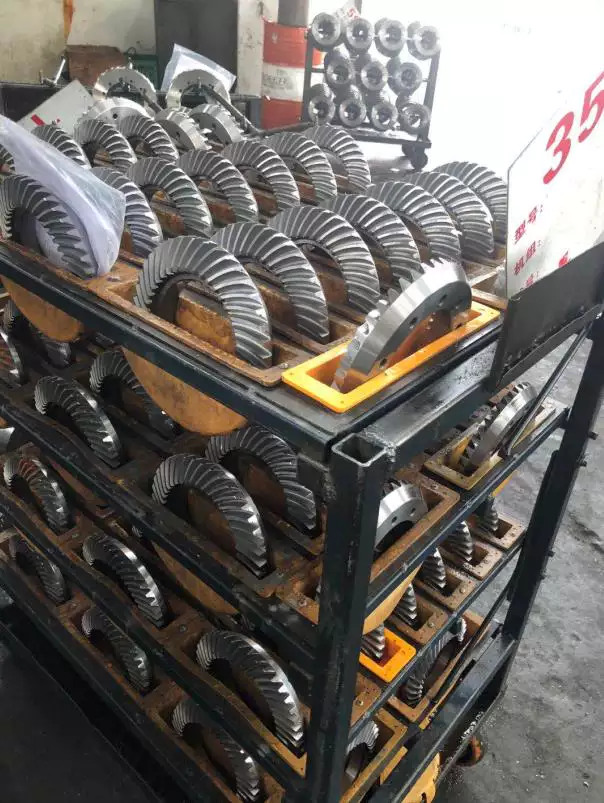
Our High-Quality Bevel Gears
We produce top-notch bevel gears with several unique features:
- High Gear Precision
- Excellent Load Capacity
- Durable and Robust Material
- Ease of Installation
- Long Service Life
Different Types of Bevel Gears and Their Characteristics
Straight Bevel Gear
Straight Bevel Gears have teeth that are straight and taper towards the apex. They are simple to produce and are generally used in applications where the direction of the shaft’s rotation needs to be changed.
Spiral Bevel Gear
Spiral Bevel Gears have teeth that are curved and oblique. They provide smooth and quiet operation, making them ideal for high-speed applications.
Zerol Bevel Gear
Zerol Bevel Gears have teeth that are curved but not angled. They can be used as an intermediary between straight and spiral bevel gears.
Spiral Zerol Bevel Gear
Spiral Zerol Bevel Gears combine the characteristics of both Spiral and Zerol Bevel Gears. They can be used in applications that require both high efficiency and quiet operation.
Choosing the Right Bevel Gears
Selecting the appropriate bevel gear involves understanding certain parameters. These include the module (size of the gear tooth), number of teeth (determines gear ratio), gear ratio (relationship between the input and output speeds), pitch (distance between corresponding points on adjacent teeth), gear material (affects durability and strength), precision grade (degree of exactness), and load capacity (maximum load the gear can handle).
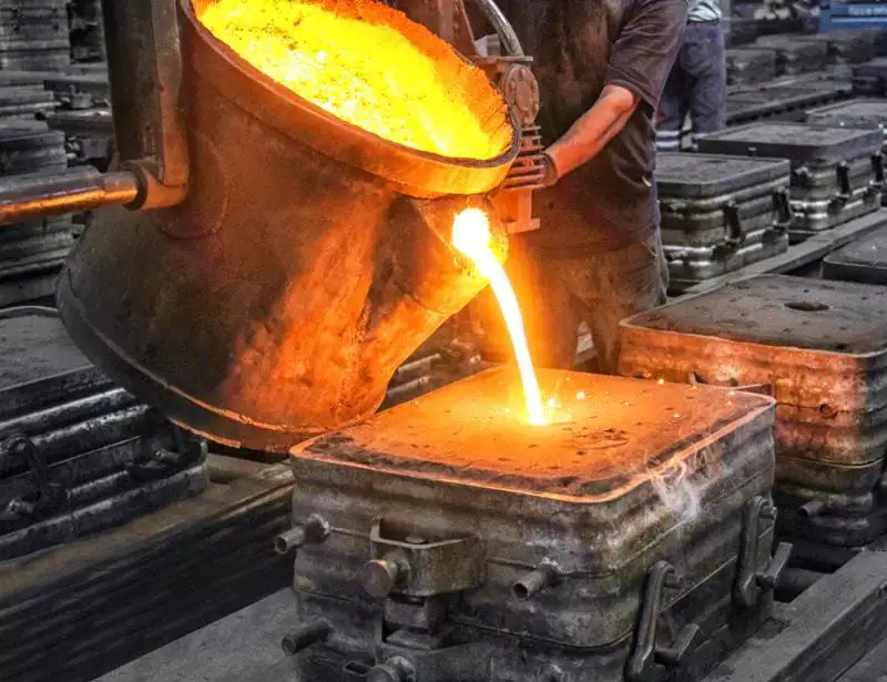
Manufacturing Process of Bevel Gears
The manufacturing process of bevel gears involves several steps, including design and engineering, material selection, cutting and machining, grinding, heat treatment, cleaning and inspection, assembly and accessory machining, surface treatment and coating, and final inspection and quality control.
Our Additional Gear and Gearbox Products
Apart from bevel gears, we offer a range of other gear and gearbox products including worm gears, helical gears, spur gears, gear racks, worm gearboxes, planetary gearboxes, and helical gearboxes.
About Us
Our company is equipped with advanced production and inspection equipment such as CNC Gear grinding machines, gear measuring machines, CNC gear shapers, machine centers, CMMS, and Torque test systems. We pride ourselves on our professionalism, international certifications, personalized services, state-of-the-art production equipment, and comprehensive after-sales service.