China Best Sales Rotary Kiln Girth Gear Custom Transmission Iron Casting Large Diameter Helical Ring Gear hypoid bevel gear
Product Description
Custom casting girth gear 42CrMo Rotary Kiln large ring gear high quality large diameter ring gear
Product Description
Process:
Forging/Casting
Normalizing&Tempering-Proof Machinnig
Quenching&Tempering
Finish Machining(Teeth Grinding)
We can offer you in various process conditions Solutions for Many End Markets and Applications
–Mining
–Metallurgy
–Power Generation
–Cement Plant
–Port Machinery
–Oil and natural
–Paper making
–OEM gear case
–General Industrial
| Specification | Machining Scope |
| Size | OD Max 16m |
| One Piece of Gear: OD Max 13m | |
| Assemble Gear: According to drawings | |
| Hobbing Modulus | 10-60 |
| Milling Modulus | Up to 120 |
| Spiral Modulus | 1-15 |
| Accuracy Grade | Milling: 6 grade |
| Hobbing: 8 grade | |
| Material | Alloy steel: 42CrMo4, 34CrNiMo6 etc. |
| Carbon steel: C45E, 1030 | |
| Carburizing steel | |
| Quenched and tempered steel | |
| Heat treatment | Quenching & Tempering, Surface Quenching |
| Teeth Profile | Spur, Helical, Herringbone, Crown, Spiral, Worm and shaft |
Inspection and Test Outline of Girth Gear:
| No. | Item | Inspection Area | Acceptance Criteria | Inspection Stage | Certificates |
| 1 | Chemical Composition | Sample | Material Requirement | When Smelting After Heat Treatment |
Chemical Composition Report |
| 2 | Mechanical Properties | Sample(Test Bar on the Gear Body) | Technical Requirement | After Heat Treatment | Mechanical Properties Report |
| 3 | Heat Treatment | Whole Body | Manufacturing Standard | During Heat Treatment | Heat Treatment Report Curves of Heat Treatment |
| 4 | Hardness Test | Tooth Surface, 3 Points Per 90° | Technical Requirement | After Heat Treatment | Hardness Teat Report |
| After Semi Finish Machining | |||||
| 5 | Dimension Inspection | Whole Body | Drawing | After Semi Finish Machining | Dimension Inspection Report |
| Finish Machining | |||||
| 6 | Magnetic Power Test (MT) | Tooth Surface | Agreed Standard | After Finish Gear Hobbing | MT Report |
| 7 | UT | Spokes Parts | Agreed Standard | After Rough Machining | UT Report |
| After Welded | |||||
| After Semi Finish Machining | |||||
| 8 | PT | Defect Area | No Defect Indicated | After Digging After Welded |
PT Record |
| 9 | Mark Inspection | Whole Body | Manufacturing Standard | Final Inspection | Pictures |
| 10 | Appearance Inspection | Whole Body | CIC’s Requirement | Before Packing (Final Inspection) |
|
| 11 | Anti-rust Inspection | Whole Body | Agreed Anti-rust Agent | Before Packing | Pictures |
| 12 | Packing Inspection | Whole Body | Agreed Packing Form | During Packing | Pictures |
Testing Process:
· QA DOC: Chemical Composition Report, Mechanical Properties Report, UT Report, Heat Treatment Report, Dimensions Check Report
· UT test: 100% ultrasonic test according to EN15718-3, SA388, Sep 1921 C/c etc.
· Heat Treatment Report: provide original copy of heat treatment curve/time table.
FAQ
1. What is your minimum order quantity?
Our minimum order quantity typically ranges from 5 to 100 pieces, depending on the product and material.
2. Can you provide custom designs?
Yes, we specialize in providing custom designs based on your specific requirements.
3. What is your production capacity?
Our production capacity varies depending on the product and material, but we have the capability to produce millions of pieces per year.
4. What is your lead time for orders?
Our lead time for orders is typically 4-6 weeks for production and delivery.
5. Do you offer quality control and testing?
Yes, we have strict quality control measures in place and offer testing services, including non-destructive testing, to ensure the quality of our products.
/* March 10, 2571 17:59:20 */!function(){function s(e,r){var a,o={};try{e&&e.split(“,”).forEach(function(e,t){e&&(a=e.match(/(.*?):(.*)$/))&&1
| Application: | Machinery, Industry |
|---|---|
| Hardness: | According to Customers′ Requirements |
| Gear Position: | Internal Gear |
.shipping-cost-tm .tm-status-off{background: none;padding:0;color: #1470cc}
|
Shipping Cost:
Estimated freight per unit. |
about shipping cost and estimated delivery time. |
|---|
| Payment Method: |
|
|---|---|
|
Initial Payment Full Payment |
| Currency: | US$ |
|---|
| Return&refunds: | You can apply for a refund up to 30 days after receipt of the products. |
|---|
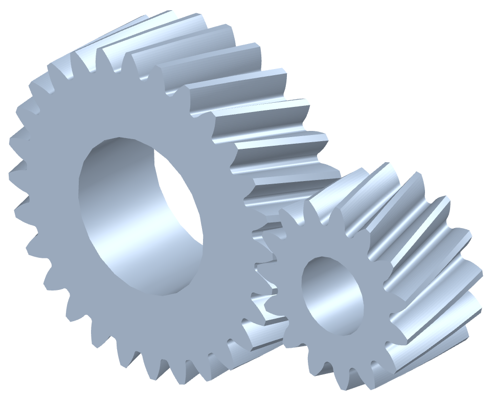
How do you maintain and service a helical gear system?
Maintaining and servicing a helical gear system is essential to ensure its long-term performance, reliability, and longevity. Proper maintenance practices help identify and address potential issues before they lead to gear failure or reduced efficiency. Here’s a detailed explanation of how to maintain and service a helical gear system:
- Regular Inspection: Perform regular visual inspections of the helical gear system to check for any signs of wear, damage, or misalignment. Inspect the gear teeth, shafts, bearings, and lubrication system for any abnormalities. Look for indications such as pitting, chipping, excessive tooth wear, or unusual noise or vibration during operation.
- Lubrication Maintenance: Ensure proper lubrication of the helical gears as per the manufacturer’s recommendations. Monitor lubricant levels, quality, and contamination. Periodically check and replenish or replace the lubricant as necessary. Follow the recommended lubrication intervals and use the appropriate lubricant type and viscosity for the operating conditions.
- Gear Cleaning: Keep the gear system clean and free from debris or contaminants. Regularly remove any accumulated dirt, dust, or foreign particles that may affect the gear performance. Use appropriate cleaning methods such as brushing, wiping, or compressed air to maintain a clean gear environment.
- Alignment Check: Misalignment can lead to premature gear failure and reduced efficiency. Periodically check the shaft alignment using precision alignment tools. Ensure that the shafts are properly aligned both radially and axially. If misalignment is detected, take corrective measures such as adjusting the shaft positions or using shims to reestablish proper alignment.
- Check Gear Meshing: Monitor the gear meshing to ensure proper tooth engagement and contact. Regularly inspect the tooth contact pattern to identify any irregularities or changes. If necessary, make adjustments to the gear position or shim thickness to achieve the desired tooth contact pattern and optimize gear performance.
- Bearing Maintenance: Check the condition of the bearings supporting the helical gears. Monitor for any signs of wear, damage, or inadequate lubrication. Replace worn-out or faulty bearings promptly to prevent further damage to the gear system. Follow the manufacturer’s guidelines for bearing maintenance, lubrication, and replacement.
- Vibration Analysis: Perform periodic vibration analysis to detect any abnormal vibration patterns that may indicate gear or bearing problems. Use vibration monitoring tools and techniques to identify the source and severity of the vibrations. If excessive vibrations are detected, investigate and rectify the underlying causes to prevent gear damage or failure.
- Temperature Monitoring: Monitor the temperature of the helical gear system during operation. Excessive heat can be an indication of inadequate lubrication, overloading, or other issues. Regularly measure and record the gear system’s operating temperature to identify any abnormal temperature rise and take appropriate action if necessary.
- Training and Documentation: Ensure that maintenance personnel are properly trained in helical gear system maintenance and servicing. Maintain detailed documentation of maintenance activities, including inspection records, lubrication schedules, and any repairs or replacements performed. This documentation helps track the gear system’s history and assists in troubleshooting and future maintenance planning.
- Consult with Experts: When in doubt or when dealing with complex gear systems, consult with gear manufacturers, industry experts, or experienced engineers for guidance on specific maintenance procedures or troubleshooting techniques. They can provide valuable insights and recommendations based on their expertise and experience.
By following these maintenance and servicing practices, you can ensure the optimal performance, reliability, and longevity of your helical gear system. Regular inspections, proper lubrication, alignment checks, and timely repairs or replacements are crucial for minimizing downtime, extending gear life, and maximizing the efficiency of the gear system.
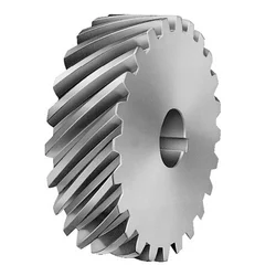
How do you address thermal expansion and contraction in a helical gear system?
Addressing thermal expansion and contraction in a helical gear system is crucial to ensure proper operation and prevent potential issues such as misalignment, increased backlash, or premature wear. Thermal expansion and contraction occur when temperature changes cause the gear components to expand or contract, affecting the gear meshing and overall performance. Here is a detailed explanation of how to address thermal expansion and contraction in a helical gear system:
- Material Selection: Choose materials for the gear components that have a similar coefficient of thermal expansion. Matching the coefficients of thermal expansion helps minimize the differential expansion and contraction between the gears, reducing the potential for misalignment or excessive clearance. Consult material suppliers or engineering references for guidance on selecting compatible materials.
- Design Considerations: Incorporate design features that account for thermal expansion and contraction. For example, provide adequate clearance between gear components to accommodate expansion without causing interference. Use proper tolerances and fits to allow for thermal variations. Consider incorporating expansion joints or flexible couplings in the system to absorb thermal movements and prevent stress concentrations.
- Operating Temperature Range: Determine the expected operating temperature range for the helical gear system. Consider the ambient temperature as well as any temperature fluctuations that may occur during operation. Understanding the temperature range helps in selecting appropriate materials and designing for thermal expansion and contraction effects.
- Lubrication: Proper lubrication is essential to address thermal expansion and contraction. Select lubricants that have good thermal stability and can maintain their viscosity within the expected temperature range. Lubricants with high thermal stability can help minimize the risk of viscosity changes, which can affect gear meshing characteristics and increase friction and wear.
- Preheating or Precooling: In some cases, preheating or precooling the gear components before assembly can help minimize the effects of thermal expansion and contraction. By bringing the components to a uniform temperature, the differential expansion can be reduced, resulting in better gear meshing alignment. However, this approach may not be suitable for all applications and should be evaluated based on the specific system requirements.
- Thermal Analysis and Simulation: Conduct thermal analysis and simulation of the helical gear system to evaluate the effects of temperature changes on gear performance. Finite element analysis (FEA) or specialized gear design software can be used to model the gear system and simulate thermal expansion and contraction. This analysis can provide insights into potential issues and guide design modifications or material selection.
- Monitoring and Maintenance: Regularly monitor the helical gear system for any signs of abnormal wear, noise, or misalignment. Implement a maintenance program that includes periodic inspections, lubricant analysis, and gear condition monitoring. Detecting early signs of thermal expansion- or contraction-related issues allows for timely corrective actions to be taken, minimizing the risk of equipment failure or reduced performance.
By considering these measures, it is possible to address thermal expansion and contraction in a helical gear system and ensure its reliable and efficient operation. Proper material selection, design considerations, lubrication, and monitoring contribute to minimizing the potential adverse effects of temperature variations on gear performance and extending the system’s lifespan.
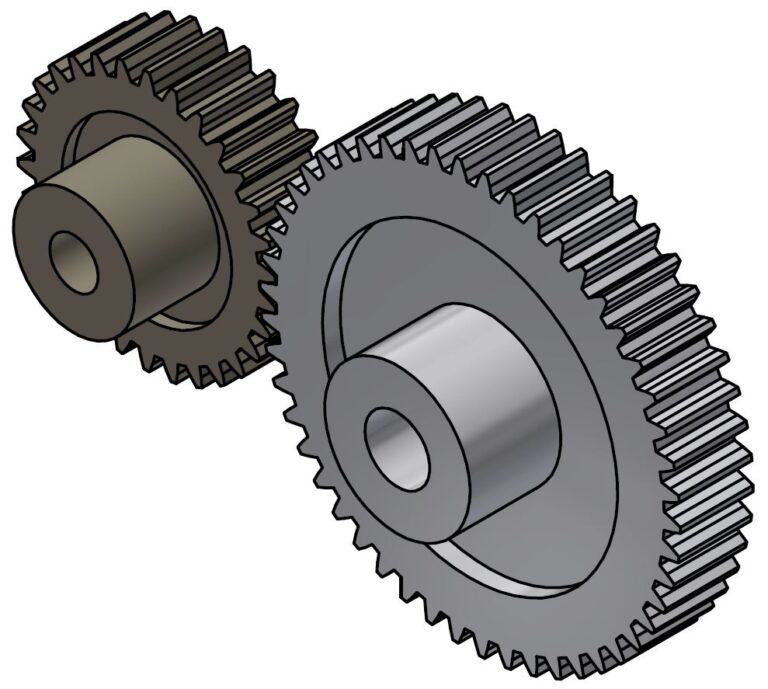
How do helical gears differ from other types of gears?
Helical gears possess distinct characteristics that set them apart from other types of gears. Here’s a detailed explanation of how helical gears differ from other gear types:
1. Tooth Orientation: Unlike spur gears, which have teeth perpendicular to the gear axis, helical gears have teeth that are cut at an angle to the gear axis. This helical tooth orientation enables gradual engagement and disengagement of the gear teeth, resulting in smoother and quieter operation.
2. Contact Pattern: Helical gears have a larger contact area compared to spur gears. The helical tooth design allows for multiple teeth to be in contact simultaneously, distributing the load across a broader surface. This increased contact pattern enhances load-carrying capacity and improves the gear’s ability to transmit higher torque.
3. Tooth Engagement: In helical gears, the teeth gradually mesh as they come into contact during rotation. This gradual engagement reduces the impact and noise typically associated with spur gears. The sliding action between the helical teeth also generates axial forces, resulting in a thrust load along the gear axis.
4. Load Distribution: The helical tooth orientation enables load distribution along the tooth face. This characteristic helps minimize localized stress concentrations and tooth wear, resulting in improved gear durability and longevity.
5. Power Transmission Efficiency: Helical gears offer high power transmission efficiency due to their larger contact area and gradual tooth engagement. The sliding action between the teeth introduces some axial force and axial thrust, which must be properly supported, but overall, helical gears are efficient in transmitting power.
6. Parallel Shaft Alignment: Helical gears are primarily used for parallel shaft applications. They transmit motion and power between parallel shafts with a constant speed ratio. Other gear types, such as bevel gears or worm gears, are better suited for non-parallel shaft arrangements or specific motion requirements.
7. Noise and Vibration: Compared to spur gears, helical gears produce less noise and vibration due to their gradual tooth engagement. The helical tooth design reduces the impact and noise caused by abrupt contact between gear teeth, resulting in smoother and quieter operation.
8. Manufacturing Complexity: Helical gears are more complex to manufacture compared to spur gears due to the helical tooth profile. The angled teeth require specialized cutting tools and machining processes. This complexity can affect the manufacturing cost and lead time of helical gears.
9. Axial Thrust Load: Helical gears generate axial forces and thrust loads due to the sliding action between the teeth. This axial thrust must be considered and properly supported in the gear system design to ensure smooth operation and prevent excessive wear or failure.
10. Application Range: Helical gears are versatile and find applications across various industries. They are commonly used in power transmission, robotics, machine tools, automotive systems, and other mechanical systems that require precise motion control and high torque transmission.
In summary, helical gears differ from other gear types in terms of tooth orientation, contact pattern, tooth engagement, load distribution, power transmission efficiency, shaft alignment suitability, noise and vibration characteristics, manufacturing complexity, axial thrust load, and application range. These unique characteristics make helical gears well-suited for specific applications where smooth operation, high load-carrying capacity, and precise motion control are required.


editor by CX 2024-01-04