China Standard Custom Stainless Steel/ Brass/ Nylon/ Plastic/ POM Straight Pinion Spur Gear Helical Gear Bevel Gear hypoid bevel gear
Product Description
Product Description
Spur Gear/ Helical Gear/ Straight Bevel Gear/ Spiral Bevel Gear/ Worm Gear
With more than 10yeas experience in the field of gear manufacturing, CHINAMFG can supply various kinds of gears, such like Spur Gear/ Helical Gear/ Straight Bevel Gear/ Spiral Bevel Gear/ Worm Gear. It’s equipped with CNC gear hobbing machines, CNC helical gear broaching machines, gear grinding machines and so on, and also equipped with testing equipment, such like gear profile measuring instrument, and hardness testing instrument. It has strong manufacturing ability and quality control ability, enable to supply good quality gears for customer.
| Modulus | M0.5-M12 |
| Processing machine | Forging, Machining, Hobbing teeth, Milling teeth, Shaving teeth, Grinding teeth….… |
| Material | 20CrMnTi/ 20CrMnMo/ 42CrMo/ C45/ 40Cr/ SS304/Brass…… |
| Heat treattment | Carburizing and quenching/ Tempering/ Nitriding/ Carbonitriding/ Induction hardening |
| Hardness | 58-62HRC |
| Qaulity standerd | GB/ DIN/ JIS/ AGMA |
| Accuracy class | 5-8 class |
Spur gear Helical gear Spiral gear
Bevel gear Internal gear ring Small module gear made of brass
Workshop
Equipped with CNC lathe, CNC hobbing teeth machines, CNC broaching teeth machines, CNC grinding teeth machines, Carburizing and Quenchin euqipments, Teeth profile measuring instruments……
Workshop CNC grinding teeth machines
CNC grinding teeth machine CNC Hobbing teeth machine
Teeth profile measuring instrument Carburizing and Quenching
FAQ
Q1: Are you trading company or manufacturer ?
A: We are factory.
Q2: How long is your delivery time and shipment?
1.Sample Lead-times: 10-20 days.
2.Production Lead-times: 30-45 days after order confirmed.
Q3: What is your advantages?
1. The most competitive price and good quality.
2. Perfect technical engineers give you the best support.
3. OEM is available.
/* March 10, 2571 17:59:20 */!function(){function s(e,r){var a,o={};try{e&&e.split(“,”).forEach(function(e,t){e&&(a=e.match(/(.*?):(.*)$/))&&1
| Application: | Motor, Motorcycle, Machinery, Marine, Toy, Agricultural Machinery |
|---|---|
| Hardness: | Hardened Tooth Surface |
| Gear Position: | External Gear |
| Manufacturing Method: | Machining |
| Toothed Portion Shape: | Spur Gear |
| Material: | 42CrMo/20crmnti/C45/ 40cr |
| Samples: |
US$ 5/Piece
1 Piece(Min.Order) | |
|---|
| Customization: |
Available
| Customized Request |
|---|
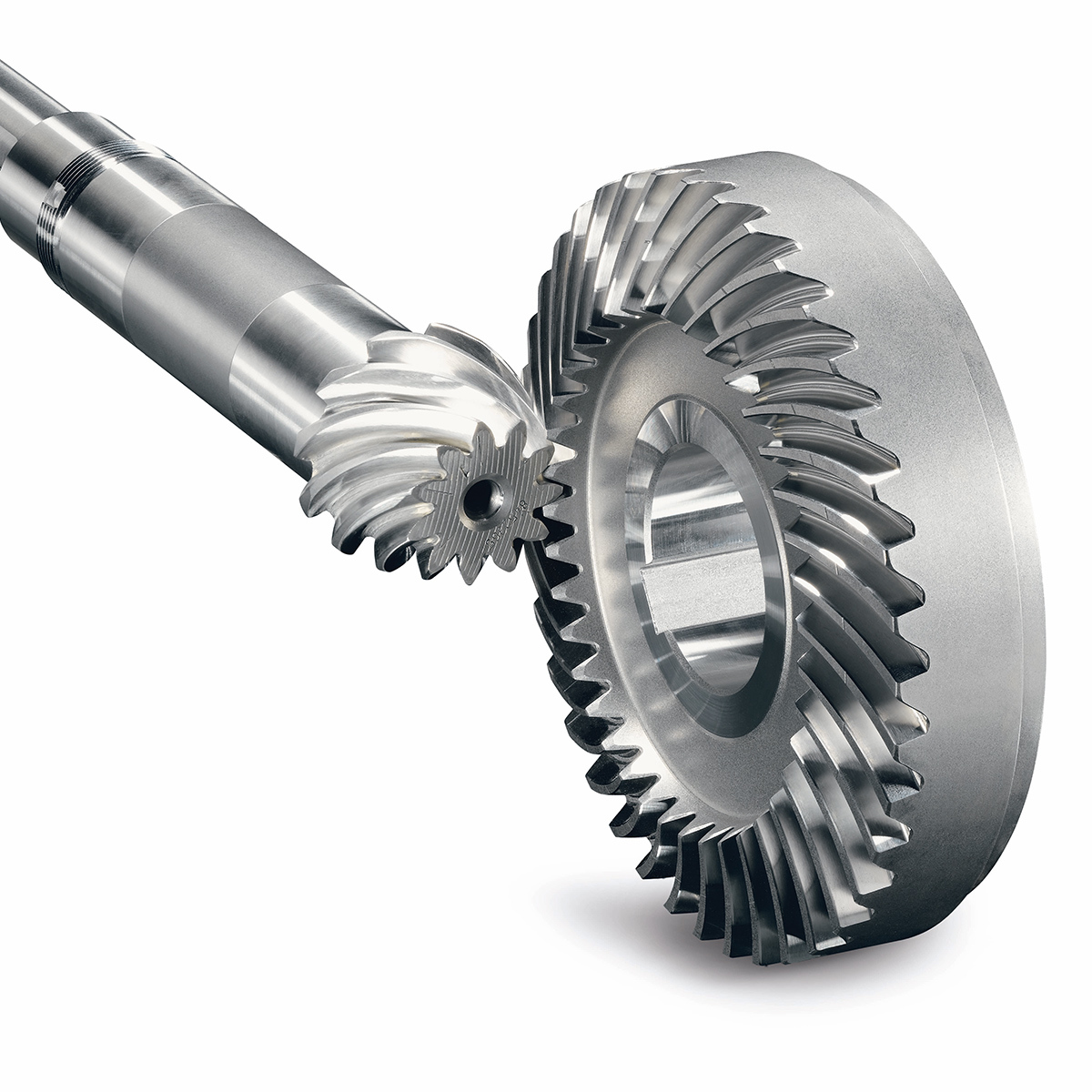
How do you install a bevel gear system?
Installing a bevel gear system involves several steps to ensure proper alignment, smooth operation, and efficient power transmission. Here’s a detailed explanation of how to install a bevel gear system:
- Preparation: Before installing the bevel gear system, gather all the necessary tools and equipment. Ensure that you have the correct bevel gears, shafts, bearings, and any additional components required for your specific application. Familiarize yourself with the system’s design, specifications, and installation instructions provided by the gear manufacturer.
- Clean and Inspect: Thoroughly clean all the components of the bevel gear system, including the gears, shafts, and bearings. Inspect them for any signs of damage, wear, or defects. Replace any damaged or worn-out parts to ensure optimal performance and longevity.
- Shaft Alignment: Proper alignment of the shafts is crucial for the bevel gear system’s performance. Ensure that the shafts are aligned accurately, both angularly and axially, as specified by the manufacturer. Misalignment can lead to premature wear, increased noise, and reduced efficiency. Use precision measurement tools, such as dial indicators, to achieve the required alignment.
- Bearing Installation: Install the bearings on the shafts according to the manufacturer’s instructions. Ensure that the bearings are securely fitted and properly lubricated. Proper bearing installation helps support the shafts, reduces friction, and ensures smooth rotation of the gears.
- Gear Meshing: Carefully position the bevel gears on the shafts, ensuring proper meshing between the teeth. The gear teeth should engage smoothly and evenly without any binding or excessive clearance. Achieving the correct gear meshing is crucial for efficient power transmission and to prevent premature wear or damage to the gears.
- Housing Assembly: Assemble the housing or casing that encloses the bevel gear system. Ensure that all housing components are aligned and securely fastened. Follow the manufacturer’s instructions for proper housing assembly, including the use of gaskets or seals to prevent lubricant leakage and contamination.
- Lubrication: Proper lubrication is essential for the smooth operation and longevity of the bevel gear system. Apply the recommended lubricant to the gears, bearings, and other moving parts according to the manufacturer’s specifications. Ensure that the lubricant used is compatible with the gear material, operating conditions, and environmental factors.
- Testing and Adjustment: After the installation is complete, perform a thorough system check. Rotate the shafts manually or using a suitable drive mechanism to ensure smooth gear operation, proper alignment, and absence of abnormal noise or vibration. Make any necessary adjustments, such as gear backlash or meshing depth, as per the manufacturer’s guidelines and based on the specific application requirements.
It’s important to note that the installation process may vary depending on the specific bevel gear system and application. Always refer to the manufacturer’s instructions and guidelines for the particular gear system you are working with to ensure proper installation and optimal performance.
In summary, installing a bevel gear system involves preparation, cleaning and inspection, shaft alignment, bearing installation, gear meshing, housing assembly, lubrication, and thorough testing and adjustment. Following proper installation procedures and adhering to manufacturer guidelines are essential to achieve efficient power transmission, smooth operation, and the desired performance from the bevel gear system.
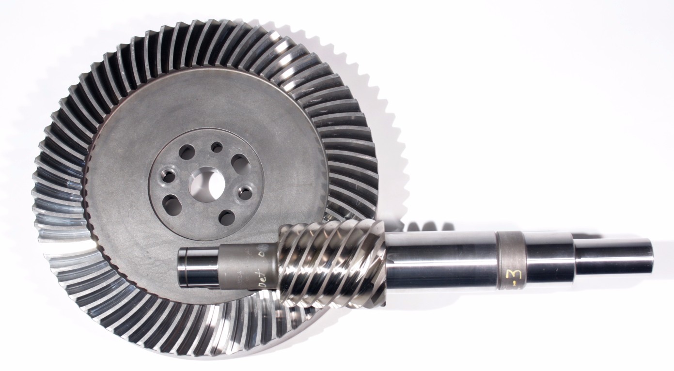
How do you retrofit an existing mechanical system with a bevel gear?
Retrofitting an existing mechanical system with a bevel gear involves modifying the system to incorporate the bevel gear for improved functionality or performance. Here’s a detailed explanation of the retrofitting process:
- Evaluate the Existing System: Begin by thoroughly evaluating the existing mechanical system. Understand its design, components, and operational requirements. Identify the specific areas where the introduction of a bevel gear can enhance the system’s performance, efficiency, or functionality.
- Analyze Compatibility: Assess the compatibility of the existing system with the integration of a bevel gear. Consider factors such as available space, load requirements, torque transmission, and alignment feasibility. Determine if any modifications or adaptations are necessary to accommodate the bevel gear.
- Design Considerations: Based on the system evaluation and compatibility analysis, develop a design plan for incorporating the bevel gear. Determine the appropriate gear type, size, and configuration that best suits the retrofitting requirements. Consider factors such as gear ratio, torque capacity, tooth profile, and mounting options.
- Modify Components: Identify the components that need modification or replacement to integrate the bevel gear. This may involve machining new shafts or shaft extensions, modifying housing or mounting brackets, or adapting existing components to ensure proper alignment and engagement with the bevel gear.
- Ensure Proper Alignment: Proper alignment is crucial for the successful integration of the bevel gear. Ensure that the existing system components and the bevel gear are aligned accurately to maintain smooth and efficient power transmission. This may involve adjusting shaft positions, aligning bearing supports, or employing alignment fixtures during the retrofitting process.
- Lubrication and Sealing: Consider the lubrication requirements of the bevel gear system. Ensure that appropriate lubricants are selected and provisions for lubrication are incorporated into the retrofit design. Additionally, pay attention to sealing arrangements to prevent lubricant leakage or ingress of contaminants into the gear system.
- Testing and Validation: After the retrofitting process is complete, conduct thorough testing and validation of the modified mechanical system. Ensure that the bevel gear functions as intended and meets the desired performance requirements. Perform functional tests, load tests, and monitor the system for any abnormalities or issues.
- Maintenance and Documentation: Develop a maintenance plan for the retrofitted system, including periodic inspection, lubrication, and any specific maintenance tasks related to the bevel gear. Document the retrofitting process, including design modifications, component specifications, alignment procedures, and any other relevant information. This documentation will be valuable for future reference, troubleshooting, or potential further modifications.
Retrofitting an existing mechanical system with a bevel gear requires careful planning, engineering expertise, and attention to detail. It is recommended to involve experienced gear engineers or professionals with expertise in retrofitting processes to ensure a successful integration and optimal performance of the bevel gear within the system.
By retrofitting an existing mechanical system with a bevel gear, it is possible to enhance its capabilities, improve efficiency, enable new functionalities, or address specific performance issues. Proper analysis, design, and implementation are essential to achieve a successful retrofit and realize the desired benefits of incorporating a bevel gear into the system.
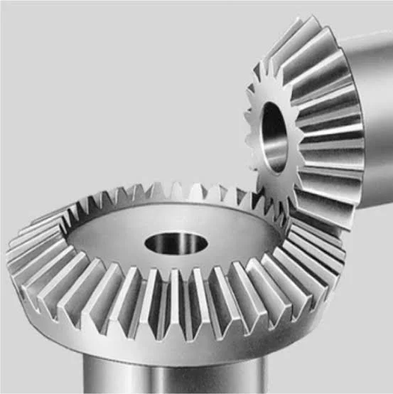
How do you calculate the gear ratio of a bevel gear?
Calculating the gear ratio of a bevel gear involves determining the ratio between the number of teeth on the driving gear (pinion) and the driven gear (crown gear). Here’s a detailed explanation of how to calculate the gear ratio of a bevel gear:
The gear ratio is determined by the relationship between the number of teeth on the pinion and the crown gear. The gear ratio is defined as the ratio of the number of teeth on the driven gear (crown gear) to the number of teeth on the driving gear (pinion). It can be calculated using the following formula:
Gear Ratio = Number of Teeth on Crown Gear / Number of Teeth on Pinion Gear
For example, let’s consider a bevel gear system with a crown gear that has 40 teeth and a pinion gear with 10 teeth. The gear ratio can be calculated as follows:
Gear Ratio = 40 / 10 = 4
In this example, the gear ratio is 4:1, which means that for every four revolutions of the driving gear (pinion), the driven gear (crown gear) completes one revolution.
It’s important to note that the gear ratio can also be expressed as a decimal or a percentage. For the example above, the gear ratio can be expressed as 4 or 400%.
Calculating the gear ratio is essential for understanding the speed relationship and torque transmission between the driving and driven gears in a bevel gear system. The gear ratio determines the relative rotational speed and torque amplification or reduction between the gears.
It’s worth mentioning that the gear ratio calculation assumes ideal geometries and does not consider factors such as backlash, efficiency losses, or any other system-specific considerations. In practical applications, it’s advisable to consider these factors and consult gear manufacturers or engineers for more accurate calculations and gear selection.
In summary, the gear ratio of a bevel gear is determined by dividing the number of teeth on the crown gear by the number of teeth on the pinion gear. The gear ratio defines the speed and torque relationship between the driving and driven gears in a bevel gear system.


editor by CX 2024-01-05