China Professional Customized Gear Large Module C45 Steel Herringbone Gear Manufacturer Steel Herringbone Gear bevel spiral gear
Product Description
Key attributes
Other attributes
Applicable Industries
Manufacturing Plant, Machinery Repair Shops, Energy & Mining
Weight (KG)
1650
Showroom Location
None
Video outgoing-inspection
Provided
Machinery Test Report
Provided
Marketing Type
Hot Product 2571
Warranty of core components
1 Year
Core Components
Gear
Place of CHINAMFG
ZheJiang , China
Condition
New
Warranty
1.5 years
Shape
Ring Gear
Standard or Nonstandard
Nonstandard
Tooth Profile
Spur
Material
Steel
Processing
Casting
Pressure Angle
20°
Brand Name
HangZhou
Product Name
custom large diameter alloy steel spur casting large ring gear
Application
Cement kiln
Gear Machining
Gear milling
Module of Gear:
8-120
OD For Gear Wheel:
MAX.13 000 mm
Height For CHINAMFG
MAX. 1200 mm
Certificate
ISO 9001:2015
Tolerance
+/-0.01mm
Heat treatment
QT
Surface Treatment
Surface Hardening or Carburizing and Quenching
Packaging and delivery
Packaging Details
Package for Cement kiln custom large diameter ring gear transmission alloy steel spur casting large ring gear is wooden box and adapts to CHINAMFG transport
Port
ZheJiang ,HangZhou or Others
Supply Ability
Supply Ability
9000 Ton/Tons per Year
OUR WORKSHOPS
OUR EQUIPMENTS
Technology Process
|
Material |
Carbon steel,Alloy steel |
||
|
Structure |
Forging,casting |
||
|
Type of gear |
spur gear,helical gear,Planetary Gear |
||
|
Heat treatment |
Quenching and tempering |
||
|
Process |
forging, rough machining, QT, finish machining |
||
|
Main equipments |
hobbing,CNC machine |
||
|
Module |
up to 200 |
||
|
Precision of gear |
Grinding ISO Grade 5-7 & Hobbing ISO Grade 8-9 |
||
|
Inspection |
Raw material inspection, UT,physical property test,dimension inspect |
||
|
Application |
Mining machinery, mill, kiln and other equipment |
||
OUR CERTIFICATE
OUR CUSTOMER FEEDBACK
CONTACT
/* January 22, 2571 19:08:37 */!function(){function s(e,r){var a,o={};try{e&&e.split(“,”).forEach(function(e,t){e&&(a=e.match(/(.*?):(.*)$/))&&1
| Application: | Industry |
|---|---|
| Hardness: | Hb190-Hb300 |
| Gear Position: | External Gear |
| Samples: |
US$ 100/Piece
1 Piece(Min.Order) | Order Sample |
|---|
| Customization: |
Available
| Customized Request |
|---|
.shipping-cost-tm .tm-status-off{background: none;padding:0;color: #1470cc}
| Shipping Cost:
Estimated freight per unit. |
about shipping cost and estimated delivery time. |
|---|
| Payment Method: |
|
|---|---|
|
Initial Payment Full Payment |
| Currency: | US$ |
|---|
| Return&refunds: | You can apply for a refund up to 30 days after receipt of the products. |
|---|
How do you choose the right size herringbone gear for your application?
Choosing the right size herringbone gear for your application involves considering several factors and performing engineering calculations. Here’s a detailed explanation of the steps involved in selecting the appropriate size herringbone gear:
- Determine the Application Requirements: Start by understanding the specific requirements of your application. Consider factors such as the input and output speeds, torque loads, power requirements, duty cycle, and operating conditions. Determine the desired service life, efficiency, and reliability expectations for the gear system.
- Calculate the Gear Ratios: Determine the required gear ratios based on the speed and torque requirements of your application. Gear ratios define the relationship between the rotational speeds and torques of the input and output shafts. Select appropriate gear ratios that fulfill the desired performance objectives.
- Calculate the Load and Torque: Estimate the maximum load and torque that the herringbone gear will experience during operation. Consider both static and dynamic loads, shock loads, and any potential overload conditions. Calculate the required torque capacity of the gear system based on these load considerations.
- Consider the Size and Space Constraints: Evaluate the available space and size constraints in your application. Measure the available distance for gear installation, including the gear’s diameter, width, and axial length. Consider any restrictions on the gear’s physical dimensions and ensure that the selected gear size fits within the available space.
- Determine the Gear Module: The gear module is a parameter that defines the size and number of gear teeth. Calculate the gear module based on the desired gear ratios, torque capacity, and available space. The gear module is typically determined by considering a balance between gear tooth strength, contact ratio, and manufacturing feasibility.
- Perform Gear Design Calculations: Utilize standard gear design formulas and calculations to determine the required number of gear teeth, pitch diameter, helix angles, and other gear dimensions. Consider factors such as gear tooth strength, contact ratio, tooth profile optimization, and gear manufacturing standards. These calculations ensure that the selected gear size can handle the anticipated loads and provide reliable performance.
- Consult Manufacturers and Standards: Consult gear manufacturers, industry standards, and guidelines to ensure compliance with best practices and safety requirements. Manufacturers can provide technical expertise, recommend suitable gear sizes, and offer guidance on material selection, heat treatment processes, and gear quality standards.
- Consider Cost and Availability: Evaluate the cost implications and availability of the selected gear size. Consider factors such as material costs, manufacturing complexity, lead times, and the overall economic feasibility of the gear system. Balance the desired performance with cost considerations to arrive at an optimal gear size.
It’s important to note that selecting the right size herringbone gear requires expertise in gear design and engineering. If you lack the necessary knowledge, it is advisable to consult with experienced gear engineers or manufacturers who can assist in the selection process.
In summary, choosing the right size herringbone gear involves determining the application requirements, calculating gear ratios and torque loads, considering size constraints, determining the gear module, performing gear design calculations, consulting manufacturers and standards, and considering cost and availability. Following these steps ensures that the selected herringbone gear size meets the specific needs of your application and provides reliable and efficient operation.
How does a herringbone gear impact the overall efficiency of a system?
Herringbone gears can have a significant impact on the overall efficiency of a mechanical system. Their unique design and characteristics contribute to improved efficiency in several ways. Here’s a detailed explanation of how herringbone gears can influence the efficiency of a system:
- Reduced Friction: Herringbone gears are designed to minimize friction between the gear teeth during operation. The double helical arrangement of the teeth allows for opposing helix angles, which helps to cancel out the axial thrust generated by the gear meshing. This results in reduced sliding friction and less energy loss due to frictional forces, thereby improving overall efficiency.
- Smooth Operation: The herringbone gear design enables smooth and precise gear engagement. The opposing helix angles of the teeth facilitate the gradual meshing and unmeshing of the gears, reducing impact and shock loads. The smooth operation minimizes vibrations and noise levels, eliminating energy losses associated with excessive vibrations and improving the overall efficiency of the system.
- Higher Torque Capacity: Herringbone gears have a larger surface area of contact between the gear teeth compared to conventional spur gears. This increased contact area allows for higher torque transmission capabilities. By efficiently transmitting higher torque loads, herringbone gears help reduce the need for additional gear stages or larger gear sizes, resulting in a more compact and efficient system.
- Better Load Distribution: The double helical arrangement of the teeth in herringbone gears helps distribute the load more evenly across the gear face. This improved load distribution minimizes localized stress concentrations and wear on the gear teeth, leading to enhanced durability and reduced energy losses due to gear wear and failure.
- Efficient Power Transmission: Herringbone gears facilitate efficient power transmission by ensuring a high degree of gear meshing contact and proper alignment. The precise gear engagement reduces backlash and ensures optimal power transfer between the gears, resulting in higher transmission efficiency and minimal power losses within the system.
- Reduced Heat Generation: Herringbone gears’ smooth operation and reduced friction contribute to lower heat generation during gear meshing. The reduced heat generation helps to minimize thermal losses within the system. Additionally, the improved load distribution and larger contact area of herringbone gears help dissipate heat more effectively, further enhancing the overall efficiency of the system.
It’s important to note that the overall efficiency of a system is influenced by various factors, including gear design, lubrication, alignment, and the specific application and operating conditions. While herringbone gears offer several advantages that contribute to improved efficiency, it’s crucial to consider the entire system design and optimize other components and parameters accordingly to achieve the highest overall efficiency.
What is a herringbone gear and how does it work?
A herringbone gear, also known as a double helical gear, is a specialized type of gear with a unique tooth design. Here’s a detailed explanation of what a herringbone gear is and how it works:
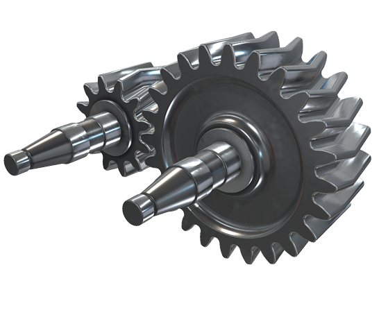
A herringbone gear consists of two helical gear sections that are mirror images of each other and are joined together to form a V-shaped or herringbone-shaped tooth profile. Unlike conventional helical gears, which have a single helix angle and a continuous spiral tooth profile, herringbone gears have two opposing helix angles, resulting in a “V” shape when viewed from the end.
The primary advantage of the herringbone gear design is its ability to eliminate axial thrust or end thrust forces that are generated in helical gears. In a conventional helical gear, the helix angle of the teeth causes an axial force along the gear’s axis during rotation. This axial force can create significant thrust loads that need to be counteracted using thrust bearings or other mechanisms.
By using the double helix design of herringbone gears, the opposing helix angles cancel out the axial forces generated by each helical section. This cancellation of axial forces eliminates the need for thrust bearings and allows herringbone gears to transmit torque smoothly without axial movement or thrust loads.
When a herringbone gear is in operation, the angled teeth of the two helical sections engage with each other, similar to how helical gears mesh. The contact between the teeth occurs gradually, starting from one end of the gear and progressing towards the other end. The overlapping or interlocking tooth profiles ensure a continuous and smooth transfer of power.
The herringbone gear design offers several advantages:
- Axial Load Balancing: The opposing helix angles in herringbone gears balance out the axial forces, eliminating the need for thrust bearings and reducing wear on the gear teeth.
- Increased Load Capacity: The V-shaped tooth profile of herringbone gears provides increased tooth contact area compared to a single helix gear. This leads to improved load distribution and higher load-carrying capacity.
- Reduced Vibration and Noise: The double helix design of herringbone gears helps cancel out vibrations and reduce noise during operation. The opposing helix angles minimize tooth deflection and ensure smoother engagement between the gear teeth.
- Bidirectional Power Transmission: Herringbone gears can transmit power in both directions due to their symmetrical tooth profiles. This makes them suitable for applications where reversing or bidirectional power transmission is required.
- High Efficiency: The continuous and gradual engagement of the herringbone gear teeth results in improved efficiency by reducing sliding friction and minimizing backlash.
Herringbone gears are commonly used in various industrial applications, including power transmission systems, heavy machinery, oil and gas equipment, marine propulsion systems, and high-speed gearboxes. Their unique design and benefits make them well-suited for applications that require high torque transmission, smooth operation, and minimal axial thrust.


editor by CX 2024-03-29