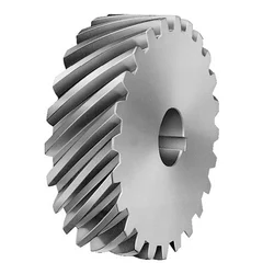
China wholesaler Yogie China Suppliers Large Module Carbon Steel Herringbone Helical Gear supplier
Product Description
Key attributes
Other attributes
Applicable Industries
Manufacturing Plant, Construction works , Energy & Mining
Weight (KG)
3000
Showroom Location
None
Video outgoing-inspection
Provided
Machinery Test Report
Provided
Marketing Type
Ordinary Product
Warranty of core components
Not Available
Core Components
Gear, Ring Gear
Place of CHINAMFG
ZheJiang , China
Condition
New
Warranty
1year
Shape
Ring Gear
Standard or Nonstandard
Nonstandard
Tooth Profile
Helical Gear,spur gear
Material
Steel
Processing
Forging
Pressure Angle
custom
Brand Name
TS
Product Name
Large Ring Gear
Module No.
5-180
Process
Milling,hobbing
Surface treatment
as request
Heat treatment
Q&T
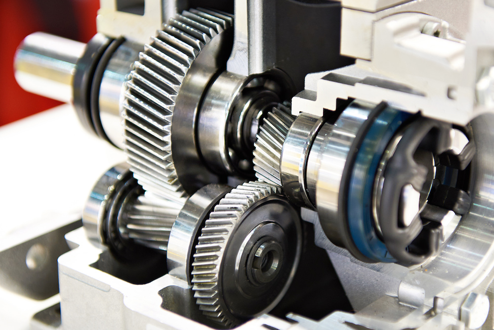
Application
Industry machinery,transmission equipment
Standard
DIN ANSI ISO
Certificate
ISO
OEM Service
YES
Delivery time
15-60days
Packaging and delivery
Packaging Details
Package adapting to CHINAMFG transport
Port
ZheJiang ,HangZhou
Supply Ability
Supply Ability
5 Piece/Pieces per Month
OUR WORKSHOPS
OUR EQUIPMENTS
Technology Process
|
Material |
Carbon steel,Alloy steel |
||
|
Structure |
Forging,casting |
||
|
Type of gear |
spur gear,helical gear,Planetary Gear |
||
|
Heat treatment |
Quenching and tempering |
||
|
Process |
forging, rough machining, QT, finish machining |
||
|
Main equipments |
hobbing,CNC machine |
||
|
Module |
up to 200 |
||
|
Precision of gear |
Grinding ISO Grade 5-7 & Hobbing ISO Grade 8-9 |
||
|
Inspection |
Raw material inspection, UT,physical property test,dimension inspect |
||
|
Application |
Mining machinery, mill, kiln and other equipment |
||
OUR CERTIFICATE
OUR CUSTOMER FEEDBACK
CONTACT
/* January 22, 2571 19:08:37 */!function(){function s(e,r){var a,o={};try{e&&e.split(“,”).forEach(function(e,t){e&&(a=e.match(/(.*?):(.*)$/))&&1
| Application: | Industry |
|---|---|
| Hardness: | Hb190-Hb300 |
| Gear Position: | External Gear |
| Samples: |
US$ 100/Piece
1 Piece(Min.Order) | Order Sample |
|---|
| Customization: |
Available
| Customized Request |
|---|
.shipping-cost-tm .tm-status-off{background: none;padding:0;color: #1470cc}
| Shipping Cost:
Estimated freight per unit. |
about shipping cost and estimated delivery time. |
|---|
| Payment Method: |
|
|---|---|
|
Initial Payment Full Payment |
| Currency: | US$ |
|---|
| Return&refunds: | You can apply for a refund up to 30 days after receipt of the products. |
|---|
How do you prevent backlash and gear play in a helical gear mechanism?
In a helical gear mechanism, preventing backlash and gear play is crucial to ensure accurate motion control, minimize vibration, and maintain the overall efficiency of the system. Here’s a detailed explanation of how to prevent backlash and gear play in a helical gear mechanism:
- Proper Gear Pair Alignment: Ensuring proper alignment of the gear pairs is essential to minimize backlash and gear play. Precise alignment helps to achieve optimal contact between the helical gear teeth, reducing gaps and potential for play. Proper alignment can be achieved through accurate positioning of the gear shafts and the use of alignment tools, such as dial indicators or laser alignment systems.
- Preload or Axial Play Adjustment: Applying a preload to the helical gears can help eliminate backlash and gear play. Preload refers to the intentional application of a force that compresses the gear mesh, ensuring a tight fit between the gear teeth. This can be achieved by using adjustable bearings, shims, or axial play adjustment mechanisms to control the axial position of the gears. By applying an appropriate preload, the gear teeth are kept in constant contact, minimizing any play or backlash.
- Accurate Gear Tooth Profile: High-quality manufacturing and accurate tooth profile design are essential to minimize backlash and gear play. The tooth profile should be precisely calculated to ensure proper engagement and minimal clearance between the gear teeth. This includes considerations such as the helix angle, tooth thickness, and tooth contact pattern. By using well-designed gear teeth with tight tolerances, backlash and gear play can be significantly reduced.
- Proper Gear Mesh Lubrication: Adequate lubrication is critical to reduce friction, wear, and the potential for backlash in helical gears. The lubricant helps to create a thin film between the mating gear surfaces, ensuring smooth and consistent gear meshing. Proper lubrication also helps to dissipate heat generated during operation, preventing gear tooth damage. The selection of a suitable lubricant and regular maintenance of the lubrication system are essential to prevent backlash and ensure optimal gear performance.
- Stiff Gearbox Design: A stiff and rigid gearbox design can help minimize gear play and backlash. The gearbox housing and supporting structures should be designed to withstand the forces and loads generated during operation. This prevents any flexing or movement of the gear components, ensuring stable gear meshing and minimizing the potential for backlash. Stiffening measures can include using robust materials, adequate bracing, and reinforcing the gearbox housing.
- Regular Maintenance and Inspection: Regular maintenance and inspection of the helical gear mechanism are essential to prevent backlash and gear play. This includes checking for any signs of wear, misalignment, or damage in the gear teeth, bearings, and housing. Any worn or damaged components should be promptly replaced to maintain the integrity of the gear system. Regular lubrication and cleanliness of the gears also contribute to minimizing backlash and ensuring smooth operation.
By implementing these preventive measures, engineers can effectively minimize backlash and gear play in a helical gear mechanism. This results in improved precision, reduced vibration, and enhanced overall efficiency of the gear system.
How do you address noise and vibration issues in a helical gear system?
In a helical gear system, addressing noise and vibration issues is crucial to ensure smooth and quiet operation, minimize component wear, and enhance overall system performance. Here’s a detailed explanation of how to address noise and vibration issues in a helical gear system:
- Proper Gear Design: The design of the helical gears can significantly impact noise and vibration levels. Design considerations such as the helix angle, tooth profile modification, and gear tooth contact pattern optimization can help minimize gear noise and vibration. A well-designed gear system with proper tooth geometry and accurate alignment reduces the likelihood of gear meshing irregularities that contribute to noise and vibration.
- Precision Manufacturing: High-quality manufacturing processes are essential to minimize noise and vibration in helical gear systems. Precise gear cutting techniques, such as hobbing or grinding, ensure accurate tooth profiles, which help reduce gear meshing deviations and associated noise. Additionally, maintaining tight manufacturing tolerances and surface finishes on gear components can help minimize vibration caused by irregularities or imperfections.
- Alignment and Assembly: Proper alignment and assembly of the helical gears are critical to minimize noise and vibration. Ensuring precise alignment of the gear shafts and gear meshing is essential to achieve optimal contact between the gear teeth. The use of alignment tools, such as dial indicators or laser alignment systems, can aid in achieving accurate alignment. Additionally, proper assembly techniques, including appropriate gear backlash and preload adjustment, can help minimize noise and vibration by optimizing gear meshing conditions.
- Optimal Lubrication: Proper lubrication is vital for reducing noise and vibration in a helical gear system. Adequate lubrication creates a thin film between the gear teeth, minimizing friction and wear. The lubricant also helps to dampen vibrations and dissipate heat generated during gear operation. Using the correct lubricant type, viscosity, and maintaining proper lubricant levels are essential for noise and vibration control.
- Stiffness of Gearbox Housing: The stiffness and rigidity of the gearbox housing influence noise and vibration levels in a helical gear system. A robust and well-designed housing structure helps to minimize the transmission of vibrations from the gears to the surrounding environment. It is important to ensure that the gearbox housing is adequately braced and supported to reduce resonances and vibrations that can contribute to noise.
- Vibration Damping: Implementing vibration damping techniques can help mitigate noise and vibration in a helical gear system. This can include the use of vibration-absorbing materials, such as elastomers or damping pads, at appropriate locations within the gear system. These materials help absorb and dissipate vibrations, reducing noise transmission and minimizing gear system resonance.
- Condition Monitoring and Maintenance: Regular condition monitoring and maintenance practices are essential for identifying and addressing noise and vibration issues in a helical gear system. Periodic inspections, including vibration analysis, can detect any abnormal vibration patterns or wear indications. Timely maintenance, such as addressing misalignment, worn components, or inadequate lubrication, can prevent further deterioration and reduce noise and vibration levels.
By implementing these measures, engineers can effectively address noise and vibration issues in a helical gear system, resulting in quieter operation, reduced component wear, and improved overall system performance.

How do helical gears differ from other types of gears?
Helical gears possess distinct characteristics that set them apart from other types of gears. Here’s a detailed explanation of how helical gears differ from other gear types:
1. Tooth Orientation: Unlike spur gears, which have teeth perpendicular to the gear axis, helical gears have teeth that are cut at an angle to the gear axis. This helical tooth orientation enables gradual engagement and disengagement of the gear teeth, resulting in smoother and quieter operation.
2. Contact Pattern: Helical gears have a larger contact area compared to spur gears. The helical tooth design allows for multiple teeth to be in contact simultaneously, distributing the load across a broader surface. This increased contact pattern enhances load-carrying capacity and improves the gear’s ability to transmit higher torque.
3. Tooth Engagement: In helical gears, the teeth gradually mesh as they come into contact during rotation. This gradual engagement reduces the impact and noise typically associated with spur gears. The sliding action between the helical teeth also generates axial forces, resulting in a thrust load along the gear axis.
4. Load Distribution: The helical tooth orientation enables load distribution along the tooth face. This characteristic helps minimize localized stress concentrations and tooth wear, resulting in improved gear durability and longevity.
5. Power Transmission Efficiency: Helical gears offer high power transmission efficiency due to their larger contact area and gradual tooth engagement. The sliding action between the teeth introduces some axial force and axial thrust, which must be properly supported, but overall, helical gears are efficient in transmitting power.
6. Parallel Shaft Alignment: Helical gears are primarily used for parallel shaft applications. They transmit motion and power between parallel shafts with a constant speed ratio. Other gear types, such as bevel gears or worm gears, are better suited for non-parallel shaft arrangements or specific motion requirements.
7. Noise and Vibration: Compared to spur gears, helical gears produce less noise and vibration due to their gradual tooth engagement. The helical tooth design reduces the impact and noise caused by abrupt contact between gear teeth, resulting in smoother and quieter operation.
8. Manufacturing Complexity: Helical gears are more complex to manufacture compared to spur gears due to the helical tooth profile. The angled teeth require specialized cutting tools and machining processes. This complexity can affect the manufacturing cost and lead time of helical gears.
9. Axial Thrust Load: Helical gears generate axial forces and thrust loads due to the sliding action between the teeth. This axial thrust must be considered and properly supported in the gear system design to ensure smooth operation and prevent excessive wear or failure.
10. Application Range: Helical gears are versatile and find applications across various industries. They are commonly used in power transmission, robotics, machine tools, automotive systems, and other mechanical systems that require precise motion control and high torque transmission.
In summary, helical gears differ from other gear types in terms of tooth orientation, contact pattern, tooth engagement, load distribution, power transmission efficiency, shaft alignment suitability, noise and vibration characteristics, manufacturing complexity, axial thrust load, and application range. These unique characteristics make helical gears well-suited for specific applications where smooth operation, high load-carrying capacity, and precise motion control are required.


editor by Dream 2024-04-22