China best Rotary Kiln 35CrMo Large Diameter Ring Gear Casting Steel Transmission Spur Large Ring Gear gear box
Product Description
Custom casting girth gear 42CrMo Rotary Kiln large ring gear high quality large diameter ring gear
Product Description
Process:
Forging/Casting
Normalizing&Tempering-Proof Machinnig
Quenching&Tempering
Finish Machining(Teeth Grinding)
We can offer you in various process conditions Solutions for Many End Markets and Applications
–Mining
–Metallurgy
–Power Generation
–Cement Plant
–Port Machinery
–Oil and natural
–Paper making
–OEM gear case
–General Industrial
| Specification | Machining Scope |
| Size | OD Max 16m |
| One Piece of Gear: OD Max 13m | |
| Assemble Gear: According to drawings | |
| Hobbing Modulus | 10-60 |
| Milling Modulus | Up to 120 |
| Spiral Modulus | 1-15 |
| Accuracy Grade | Milling: 6 grade |
| Hobbing: 8 grade | |
| Material | Alloy steel: 42CrMo4, 34CrNiMo6 etc. |
| Carbon steel: C45E, 1030 | |
| Carburizing steel | |
| Quenched and tempered steel | |
| Heat treatment | Quenching & Tempering, Surface Quenching |
| Teeth Profile | Spur, Helical, Herringbone, Crown, Spiral, Worm and shaft |
Inspection and Test Outline of Girth Gear:
| No. | Item | Inspection Area | Acceptance Criteria | Inspection Stage | Certificates |
| 1 | Chemical Composition | Sample | Material Requirement | When Smelting After Heat Treatment |
Chemical Composition Report |
| 2 | Mechanical Properties | Sample(Test Bar on the Gear Body) | Technical Requirement | After Heat Treatment | Mechanical Properties Report |
| 3 | Heat Treatment | Whole Body | Manufacturing Standard | During Heat Treatment | Heat Treatment Report Curves of Heat Treatment |
| 4 | Hardness Test | Tooth Surface, 3 Points Per 90° | Technical Requirement | After Heat Treatment | Hardness Teat Report |
| After Semi Finish Machining | |||||
| 5 | Dimension Inspection | Whole Body | Drawing | After Semi Finish Machining | Dimension Inspection Report |
| Finish Machining | |||||
| 6 | Magnetic Power Test (MT) | Tooth Surface | Agreed Standard | After Finish Gear Hobbing | MT Report |
| 7 | UT | Spokes Parts | Agreed Standard | After Rough Machining | UT Report |
| After Welded | |||||
| After Semi Finish Machining | |||||
| 8 | PT | Defect Area | No Defect Indicated | After Digging After Welded |
PT Record |
| 9 | Mark Inspection | Whole Body | Manufacturing Standard | Final Inspection | Pictures |
| 10 | Appearance Inspection | Whole Body | CIC’s Requirement | Before Packing (Final Inspection) |
|
| 11 | Anti-rust Inspection | Whole Body | Agreed Anti-rust Agent | Before Packing | Pictures |
| 12 | Packing Inspection | Whole Body | Agreed Packing Form | During Packing | Pictures |
Testing Process:
· QA DOC: Chemical Composition Report, Mechanical Properties Report, UT Report, Heat Treatment Report, Dimensions Check Report
· UT test: 100% ultrasonic test according to EN15718-3, SA388, Sep 1921 C/c etc.
· Heat Treatment Report: provide original copy of heat treatment curve/time table.
FAQ
1. What is your minimum order quantity?
Our minimum order quantity typically ranges from 5 to 100 pieces, depending on the product and material.
2. Can you provide custom designs?
Yes, we specialize in providing custom designs based on your specific requirements.
3. What is your production capacity?
Our production capacity varies depending on the product and material, but we have the capability to produce millions of pieces per year.
4. What is your lead time for orders?
Our lead time for orders is typically 4-6 weeks for production and delivery.
5. Do you offer quality control and testing?
Yes, we have strict quality control measures in place and offer testing services, including non-destructive testing, to ensure the quality of our products.
/* January 22, 2571 19:08:37 */!function(){function s(e,r){var a,o={};try{e&&e.split(“,”).forEach(function(e,t){e&&(a=e.match(/(.*?):(.*)$/))&&1
| Application: | Machinery, Industry |
|---|---|
| Hardness: | According to Customers′ Requirements |
| Gear Position: | Internal Gear |
.shipping-cost-tm .tm-status-off{background: none;padding:0;color: #1470cc}
|
Shipping Cost:
Estimated freight per unit. |
about shipping cost and estimated delivery time. |
|---|
| Payment Method: |
|
|---|---|
|
Initial Payment Full Payment |
| Currency: | US$ |
|---|
| Return&refunds: | You can apply for a refund up to 30 days after receipt of the products. |
|---|
Can spur gears be used in precision manufacturing equipment?
Yes, spur gears can be used in precision manufacturing equipment. Here’s a detailed explanation:
Precision manufacturing equipment requires high accuracy, repeatability, and reliability to produce intricate and precise components. While other gear types like helical gears or bevel gears are commonly used in precision applications, spur gears can also be suitable in certain scenarios.
1. Low-Speed Applications:
Spur gears are well-suited for low-speed applications where high precision is required. In precision manufacturing equipment, such as milling machines, lathes, or grinding machines, where controlled and precise rotational motion is essential, spur gears can provide the necessary power transmission with accuracy.
2. Linear Actuators and Positioning Systems:
Spur gears can be used in linear actuators and positioning systems within precision manufacturing equipment. These systems require precise movement control, and spur gears can convert rotary motion into linear motion accurately. By incorporating precision-ground spur gears with proper backlash control, highly accurate positioning can be achieved.
3. Tooling Systems:
Spur gears are employed in tooling systems used in precision manufacturing equipment, such as indexing heads and rotary tables. These systems enable precise and repeatable positioning of workpieces or cutting tools. Spur gears with high precision tooth profiles and low backlash are utilized to ensure accurate tool positioning and consistent machining results.
4. Measuring and Inspection Equipment:
In precision manufacturing, gear systems are also utilized in measuring and inspection equipment. Spur gears can be incorporated into gear trains within instruments like coordinate measuring machines (CMMs) or optical comparators to translate linear or rotary motion into precise measurement data. The gear systems in these instruments require minimal backlash and high accuracy to ensure accurate measurements.
5. Customized Gear Systems:
In some cases, precision manufacturing equipment may require custom-designed gear systems to meet specific application requirements. Spur gears can be tailored and optimized for these custom gear systems, taking into account factors like gear tooth profile, material selection, and gear geometry. This allows for the creation of highly precise and specialized gear systems.
While spur gears have advantages in precision manufacturing equipment, it’s important to consider their limitations. Due to their design, spur gears may produce more noise and vibration compared to other gear types. Additionally, they are generally not suitable for high-speed or high-torque applications that demand continuous and smooth power transmission.
Overall, spur gears can be successfully used in precision manufacturing equipment for specific applications that require low-speed, precise motion control, accurate positioning, and measurement capabilities. Proper gear selection, high-quality manufacturing, and careful system integration are key to achieving the desired precision and performance in these gear applications.
How do you maintain and service a spur gear system?
Maintaining and servicing a spur gear system is crucial to ensure its optimal performance, longevity, and reliability. Here’s a detailed explanation of how to maintain and service a spur gear system:
- Regular Inspection: Perform regular inspections of the spur gear system to identify any signs of wear, damage, misalignment, or abnormal operating conditions. Inspect the gear teeth, shafts, bearings, and housing for any visible issues. Pay attention to unusual noises, vibrations, or changes in gear performance. Early detection of problems allows for timely intervention and prevents further damage.
- Cleaning: Keep the spur gear system clean by removing any dirt, debris, or contaminants that may accumulate on the gear surfaces or within the gear housing. Use appropriate cleaning methods such as brushing, wiping, or blowing with compressed air. Avoid using harsh chemicals that may damage the gear components or compromise lubrication.
- Lubrication: Ensure proper lubrication of the spur gear system as per the manufacturer’s recommendations. Regularly check the lubricant levels and condition. Monitor viscosity, contamination levels, and oxidation of the lubricant. Replenish or replace the lubricant as necessary to maintain optimal gear lubrication and protection against wear.
- Alignment Check: Periodically check the shaft alignment of the gear system to ensure proper alignment. Misaligned shafts can result in increased wear, noise, and reduced gear efficiency. Use alignment tools such as dial indicators or laser alignment systems to verify and adjust the shaft alignment if needed.
- Torque and Fastener Check: Check the torque of fasteners, including bolts, set screws, and retaining rings, to ensure they are properly tightened. Loose fasteners can lead to gear misalignment and compromised performance. Follow the manufacturer’s recommended torque values for the specific gear system components.
- Replacement of Worn Components: Over time, gear components such as gear teeth, bearings, or shafts may wear out or become damaged. Replace any worn or damaged components promptly to prevent further issues and maintain the gear system’s functionality. Use genuine replacement parts recommended by the gear manufacturer.
- Monitoring Operating Conditions: Monitor the operating conditions of the gear system, including temperature, load, and speed. Ensure that the gear system operates within the specified limits and does not exceed the design parameters. Excessive heat, overloading, or high-speed operation can accelerate wear and reduce gear life.
- Training and Expert Support: Ensure that personnel responsible for maintaining and servicing the spur gear system receive proper training and have access to expert support. Familiarize yourself with the gear system’s documentation, including maintenance manuals, technical specifications, and troubleshooting guides. Consult with gear manufacturers or specialists for guidance on specific maintenance procedures or complex issues.
Developing a regular maintenance schedule and keeping accurate records of maintenance activities can help ensure consistent and effective servicing of the spur gear system. Adhering to recommended maintenance practices and addressing any identified issues promptly will help optimize the performance, reliability, and service life of the gear system.
It’s important to note that maintenance and servicing procedures may vary depending on the specific gear system, application, and manufacturer’s recommendations. Therefore, always refer to the gear system’s documentation and consult with the manufacturer for detailed maintenance instructions.
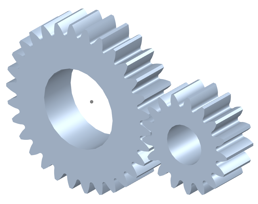
Can you explain the concept of straight-cut teeth in spur gears?
The concept of straight-cut teeth is fundamental to understanding the design and operation of spur gears. Straight-cut teeth, also known as straight teeth or parallel teeth, refer to the shape and arrangement of the teeth on a spur gear. Here’s a detailed explanation of the concept of straight-cut teeth in spur gears:
Spur gears have teeth that are cut straight and parallel to the gear axis. Each tooth has a uniform width and thickness, and the tooth profile is a straight line. The teeth are evenly spaced around the circumference of the gear, allowing them to mesh with other spur gears.
The key characteristics and concepts related to straight-cut teeth in spur gears include:
- Tooth Profile: The tooth profile of a spur gear with straight-cut teeth is a straight line that extends radially from the gear’s pitch circle. The profile is perpendicular to the gear axis and remains constant throughout the tooth’s height.
- Pitch Circle: The pitch circle is an imaginary circle that represents the theoretical point of contact between two meshing gears. For a spur gear, the pitch circle is located midway between the gear’s base circle (the bottom of the tooth profile) and the gear’s addendum circle (the top of the tooth profile).
- Pressure Angle: The pressure angle is the angle between the line tangent to the tooth profile at the pitch point and a line perpendicular to the gear axis. It determines the force distribution between the meshing teeth and affects the gear’s load-bearing capacity and efficiency. Common pressure angles for spur gears are 20 degrees and 14.5 degrees.
- Meshing: Straight-cut teeth in spur gears mesh directly with each other. The teeth engage and disengage along a line contact, creating a point or line contact between the contacting surfaces. This direct meshing arrangement allows for efficient power transmission and motion transfer.
- Advantages and Limitations: Straight-cut teeth offer several advantages in spur gears. They are relatively simple to manufacture, resulting in cost-effective production. Moreover, they provide efficient power transmission and are suitable for moderate to high-speed applications. However, straight-cut teeth can generate more noise and vibration compared to certain other tooth profiles, and they may experience higher stress concentrations under heavy loads.
In summary, straight-cut teeth in spur gears refer to the straight and parallel arrangement of the gear’s teeth. The teeth have a uniform profile with a constant width and thickness. Understanding the concept of straight-cut teeth is essential for designing and analyzing spur gears, considering factors such as tooth profile, pitch circle, pressure angle, meshing characteristics, and the trade-offs between simplicity, efficiency, and noise considerations.


editor by CX 2024-04-09