China Best Sales 42CrMo4 Slewing Ring Bearing Slewing Gear (07-1830-04 NN 13) gear ratio calculator
Product Description
CHINAMFG bearings is a professional manufacture of ball bearing, roller bearing, slewing ring bearing in china
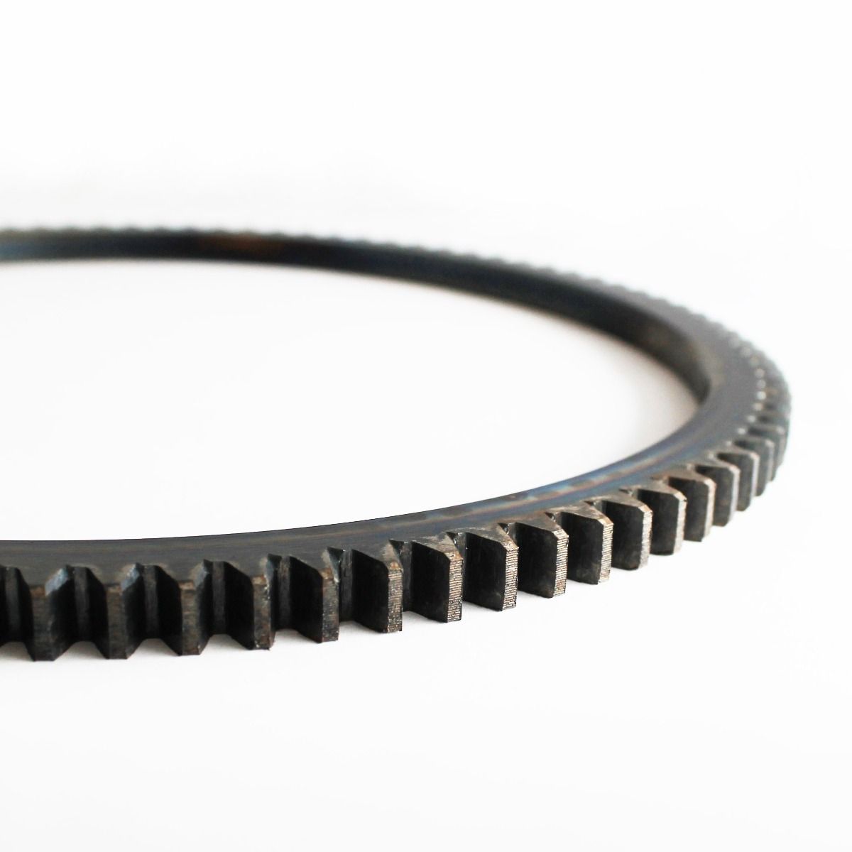
Detailed specifications for the model: 07-1830-04 NN 13
1. Type: Four point contact ball slewing ring bearing
2. Bore diameter: 1595mm
3. Outside diameter: 2002mm
4. Height: 150mm
5. Material: 42CrMo, 50Mn
6. Precision: P0. P6. P5.
7. Cage/retainer: Nylon or aluminum
8. Gear type: Internal gear
9. N. W. 1128kgs
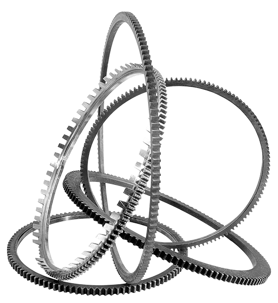
Detailed description of these types slewing bearings
Single row 4 point contact ball slewing bearings
This kind of slewing bearings can support high dynamic loads, transmitting axial and radial forces simultaneously as well as the resulting tilting moments. Applications of this kind of bearings are hoisting, mechanical handling and general mechanical engineering etc.
Single row cross roller slewing bearings
This kind of bearings can support combinations of large radial force, medium axial force and tilting moment with small or zero clearance. Main applications of this kind of bearings are hoisting and mechanical handling and general mechanical engineering etc.
Double row different ball diameter slewing bearings
This kind of bearings can support high static loads with simple structures. They are mainly used in situations with variation load position and direction and continuously rotating. Main applications of this kind of bearings are deck hoisting, mining and material handling etc.
Triple row cylindrical roller slewing bearings
This kind of bearings has high load carrying capacity. Under same loads, this kind of bearings has much smaller diameters which can make the installation much compact, as different kinds of loads are supported by different races and rollers. Main applications of this kind of bearings are hoisting, mechanical handling, mining and materials handling, offshore technology and general mechanical engineering etc.
Roller/ball combination slewing bearings
This kind of bearings can support high axial load and low tilting moments. Usually they are large diameter slewing bearings. Applications of this kind of bearings are mining and materials handling etc.
About CHINAMFG bearings
1.introduction:we are a manufacturer of slewing bearing since 1993, our factory occupies a area of 30000square meters with 4 workshop and 1 office building.
2. Featured products: slewing bearing and slewing drive
3. Capital: Current is 1 million RMB, but we are increasing the capital to 10 million RMB
4. Workers: 40
5. Certificate: ISO9001:2008, 3.1 certificate, CCS certificate, Science and Technology Progress Award
6. Annual Exportation: 8million USD
7. Exported countries: (39)
Asia: India, Pakistan, Iran, Signore, Georgia, Malaysia, Vietnam, Thailand, Philippines, Israel, Korea, UAE, Sri Lanka, Saudi Arabia,
Europe: Turkey, Russia, Spain, Czech Republic, Italy, Poland, Slovakia, Bosnia and Herzegovina, Austria, France, Germany, Switzerland, Finland, Ukraine, UK
America: USA, Canada, Mexico, Brazil, Puerto Rico, Peru, Chile
Africa: South Africa, Egypt
Oceania: Australia
Production Process of CHINAMFG slewing bearings
Quality Control Process of CHINAMFG slewing bearings
LYHY Slewing Bearing Packing
Bearing surface is covered with the anti-rust oil first; and then wrapped with the plastic film;
And then packed with kraft paper and professional belts;
At last, with wooden box totally at the outer packing to invoid the rust or the moist;
We can depend on the customers demand to be packed;
Slewing Ring Bearings——Applications:
Slewing ring bearings are widely used in industry and known as “the machine joints” Here under is the specific slewing bearing applications
1. Construction machinery (e.g. cranes, excavators, loader, scraper)
2. Metallurgical machinery (e.g. for steel plant)
3. Heavy machinery equipment (e.g. mining machinery, concrete machinery)
4. Marine machinery equipment (e.g. vessel, port hoisting machine, port oil transfer equipment, onshore and offshore crane)
5. Light machinery equipment (e.g. paper machine, plastic, rubber machine, weave machine)
6. Wind power generator
7. Packing machinery
Transportation:
All CHINAMFG slewing ring bearings can be usually delivered timely, usual production time is 15-50 days based on different slew bearings diameters, sometimes slew rings will be in stock.
Slewing bearings can be offered different delivery terms, such as EXW, FOB, CIF, DDU and so on.
Also, slewing rings can be transported by different transport ways, by express (such as DHL, TNT, UPS, FEDEX and so on), by air, by sea, by truck, by railway and so on.
FAQ:
Q: Are LYHY BEARINGS trading company or manufacturer?
A: CHINAMFG BEARINGS is a professional manufacturer for slewing bearings, thin section bearings, ball bearings and rolling bearings
Q: How do LYHY BEARINGS control quality of their bearing?
A: LYHY BEARINGS has established strict quality control systems, all the products and services has passed ISO9001-2008 Quality Certificate and third party such as CCS, LR,ABS,BV
Q: What is the MOQ?
A: MOQ is 1pc, pls message us for detailed information.
Q: How about the package for CHINAMFG bearings?
A: Standard Industrial packing in general condition (Plastic tube+ professional plastic belts+ plywood case). Accept design package when OEM.
Q: How long is the production time?
A: It takes about 7-40 days, depends on the model and quantity.
Q: How about the shipping?
A: We can arrange the shipment or you may have your own forwarder.
Q: Is sample available?
A: Yes, sample order is acceptable.
Q: Can we use our own LOGO or design on bearings?
A: Yes. OEM is acceptable for LYHY BEARINGS. We can design as per your requirements and use your own LOGO and package design.
INSTALLATION OF CHINAMFG SLEWING BEARINGS
Preparation:
Make sure that the model is correct and slewing bearing isn’t damaged during transportation.
2. Check the appearance and rotational state of the bearing, such as rotational precision clearance, rotating flexibility, seals position, lubrication grease etc.
3. The installation datum plane and bracket installing plane should be clean, grease, burr, paint and other foreign body should be wiped off.
Installation:
1. The screws in the installing plane should be fit with the mounting holes in the slewing bearing
2. The slewing bearing has a soft zone marked with an “s” on the upper surface, when installing the bearing, it is important to ensure that this area is placed in a non-load or infrequent load zone.
3. When the bearing is placed on the supporting frame work it is important to check the interface between these 2 surfaces. This check should be carried out with the insertion of feel gauges between the 2 surfaces. If a gap should exist then it is recommended to plane/resurface the effective area so as to remove the gap.
4. Install slewing bearing with high strength screws, and choose appropriate strength bolts. All bolts are required to be tightened evenly. The sequence of this tightening process is shown in Pic. Welding of bearing is not allowed, in the event of welding any adjacent parts, heat transfer shall be avoided so as to cause the bearing to become deformed or change the hardness.
5. After installation, the bearing should be rotated to check for smooth operation and any emission of unusual noise. If either of the aforementioned are noted, then the bearing should be adjusted to eliminate them. The teeth of the largest run-out are coated with green paint.
| External Diameter | Internal Diameter | Height | Weight | Module | Gear No. | Model |
| 244 | 125 | 25 | 5 | 2 | 120 | |
| 318 | 169 | 45 | 14 | 3 | 104 | |
| 379 | 210 | 45 | 20 | 4 | 92 | |
| 403.5 | 234 | 55 | 25 | 4.5 | 88 | |
| 440 | 265 | 50 | 28 | 4.5 | 95 | |
| 505 | 304 | 56 | 32 | 5 | 99 | |
| 505 | 342 | 56 | 32 | 5 | 99 | |
| 529 | 323 | 54 | 45 | 5 | 103 | |
| 535 | 305 | 75 | 61 | 8 | 65 | |
| 589 | 383 | 75 | 62 | 5 | 116 | |
| 640 | 434 | 56 | 44 | 6 | 105 | |
| 640 | 472 | 56 | 46 | 6 | 105 | |
| 654 | 390 | 85 | 98 | 8 | 80 | |
| 689 | 455 | 74 | 89 | 6 | 112 | |
| 700 | 479 | 77 | 85 | 6 | 114 | |
| 742 | 534 | 56 | 52 | 6 | 122 | |
| 742 | 572 | 56 | 55 | 6 | 122 | |
| 774 | 516 | 82 | 118 | 8 | 94 | |
| 816 | 573 | 90 | 129 | 6 | 132 | |
| 840 | 634 | 56 | 60 | 6 | 138 | |
| 840 | 672 | 56 | 62 | 6 | 138 | |
| 863 | 679 | 82 | 102 | 6 | 142 | |
| 886 | 610 | 85 | 155 | 8 | 108 | |
| 950 | 734 | 56 | 68 | 8 | 117 | |
| 950 | 772 | 56 | 71 | 8 | 117 | |
| 979 | 717 | 100 | 178 | 10 | 94 | |
| 1571 | 770 | 82 | 159 | 8 | 125 | |
| 1046 | 834 | 56 | 76 | 8 | 129 | 21 0571 01 |
| 1046 | 872 | 56 | 78 | 8 | 129 | 31 0571 01 |
| 1094 | 833 | 82 | 179 | 8 | 134 | |
| 1144 | 869 | 100 | 228 | 10 | 111 | |
| 1198 | 984 | 56 | 86 | 8 | 148 | |
| 1198 | 1571 | 56 | 91 | 8 | 148 | |
| 1218 | 930 | 98 | 268 | 10 | 119 | |
| 1289.5 | 984 | 114 | 330 | 10 | 125 | |
| 1358 | 1045 | 98 | 325 | 10 | 133 | |
| 1431 | 1200 | 63 | 176 | 8 | 177 | |
| 1476 | 1084 | 110 | 503 | 10 | 144 | |
| 1604 | 1206 | 130 | 653 | 10 | 157 |
| External Gear | |||||||
| External Diameter | Internal Diameter | Height | Weight | Module | Gear No. | Model | * |
| 244 | 125 | 25 | 5 | 2 | 120 | STD | |
| 318 | 169 | 45 | 14 | 3 | 104 | STD | |
| 379 | 210 | 45 | 20 | 4 | 92 | STD | |
| 403.5 | 234 | 55 | 25 | 4.5 | 88 | STD | |
| 440 | 265 | 50 | 28 | 4.5 | 95 | STD | |
| 505 | 304 | 56 | 32 | 5 | 99 | SL | |
| 505 | 342 | 56 | 32 | 5 | 99 | SLBP | |
| 529 | 323 | 54 | 45 | 5 | 103 | STD | |
| 535 | 305 | 75 | 61 | 8 | 65 | STD | |
| 589 | 383 | 75 | 62 | 5 | 116 | STD | |
| 640 | 434 | 56 | 44 | 6 | 105 | SL | |
| 640 | 472 | 56 | 46 | 6 | 105 | SLBP | |
| 654 | 390 | 85 | 98 | 8 | 80 | STD | |
| 689 | 455 | 74 | 89 | 6 | 112 | STD | |
| 700 | 479 | 77 | 85 | 6 | 114 | STD | |
| 742 | 534 | 56 | 52 | 6 | 122 | SL | |
| 742 | 572 | 56 | 55 | 6 | 122 | SLBP | |
| 774 | 516 | 82 | 118 | 8 | 94 | STD | |
| 816 | 573 | 90 | 129 | 6 | 132 | STD | |
| 840 | 634 | 56 | 60 | 6 | 138 | SL | |
| 840 | 672 | 56 | 62 | 6 | 138 | SLBP | |
| 863 | 679 | 82 | 102 | 6 | 142 | STD | |
| 886 | 610 | 85 | 155 | 8 | 108 | STD | |
| 950 | 734 | 56 | 68 | 8 | 117 | SL | |
| 950 | 772 | 56 | 71 | 8 | 117 | SLBP | |
| 979 | 717 | 100 | 178 | 10 | 94 | STD | |
| 1571 | 770 | 82 | 159 | 8 | 125 | STD | |
| 1046 | 834 | 56 | 76 | 8 | 129 | 21 0571 01 | SL |
| 1046 | 872 | 56 | 78 | 8 | 129 | 31 0571 01 | SLBP |
| 1094 | 833 | 82 | 179 | 8 | 134 | STD | |
| 1144 | 869 | 100 | 228 | 10 | 111 | STD | |
| 1198 | 984 | 56 | 86 | 8 | 148 | SL | |
| 1198 | 1571 | 56 | 91 | 8 | 148 | SLBP | |
| 1218 | 930 | 98 | 268 | 10 | 119 | STD | |
| 1289.5 | 984 | 114 | 330 | 10 | 125 | STD | |
| 1358 | 1045 | 98 | 325 | 10 | 133 | STD | |
| 1431 | 1200 | 63 | 176 | 8 | 177 | STD | |
| 1476 | 1084 | 110 | 503 | 10 | 144 | STD | |
| 1604 | 1206 | 130 | 653 | 10 | 157 | STD | |
| 1605 | 1270 | 110 | 469 | 12 | 131 | STD | |
| 1727 | 1500 | 63 | 213 | 8 | 214 | STD | |
| 1836 | 1433 | 135 | 791 | 16 | 112 | STD | |
| 1929 | 1565 | 110 | 617 | 14 | 135 | STD | |
| 1975 | 1750 | 63 | 244 | 8 | 245 | STD | |
| 2571 | 1615 | 150 | 1004 | 14 | 142 | STD | |
| 2140 | 1720 | 130 | 953 | 16 | 131 | STD | |
| 2165 | 1950 | 68 | 278 | 8 | 269 | STD | |
| 2267 | 1815 | 140 | 1174 | 16 | 139 | STD | |
| 2342 | 2091 | 70 | 373 | 8 | 290 | STD | |
| 2390 | 1950 | 130 | 1111 | 18 | 130 | STD | |
| 2534 | 2042 | 144 | 1482 | 18 | 138 | STD | |
| 2695 | 2425 | 63 | 411 | 8 | 335 | STD | |
| 2790 | 2290 | 164 | 1895 | 18 | 151 | STD | |
| 3116 | 2600 | 164 | 2200 | 20 | 152 | STD | |
| 3200 | 2914 | 190 | 716 | 10 | 318 | STD | |
| Without Gear | |||||
| External Diameter | Internal Diameter | Height | Weight | Reference | * |
| 234 | 125 | 25 | 5 | STD | |
| 290 | 150 | 41.5 | 14 | STD | |
| 300 | 140 | 52 | 16 | STD | |
| 329 | 190 | 45 | 17 | STD | |
| 350 | 190 | 52 | 20 | STD | |
| 403.5 | 235 | 55 | 26 | STD | |
| 440 | 240 | 60 | 37 | STD | |
| 440 | 265 | 50 | 29 | STD | |
| 455 | 265 | 71 | 45 | STD | |
| 474 | 336 | 46 | 24 | STD | |
| 475 | 335 | 45 | 30 | STD | |
| 486 | 342 | 56 | 29 | SLBP | |
| 500 | 305 | 75 | 51 | STD | |
| 518 | 304 | 56 | 23 | SL | |
| 589 | 383 | 75 | 66 | STD | |
| 616 | 472 | 56 | 38 | SLBP | |
| 626 | 424 | 72 | 70 | STD | |
| 648 | 434 | 56 | 34 | SL | |
| 700 | 479 | 77 | 90 | STD | |
| 712 | 487 | 72 | 91 | STD | |
| 716 | 572 | 56 | 45 | SLBP | |
| 748 | 534 | 56 | 40 | SL | |
| 816 | 672 | 56 | 52 | SLBP | |
| 816 | 573 | 90 | 137 | STD | |
| 848 | 634 | 56 | 46 | SL | |
| 900 | 670 | 86 | 148 | STD | |
| 916 | 772 | 56 | 60 | SLBP | |
| 948 | 734 | 56 | 52 | SL | |
| 979 | 717 | 100 | 193 | STD | |
| 1016 | 872 | 56 | 67 | 33 0571 01 | SLBP |
| 1048 | 834 | 56 | 58 | 23 0571 01 | SL |
| 1130 | 845 | 100 | 271 | STD | |
| 1144 | 869 | 100 | 248 | STD | |
| 1166 | 1571 | 56 | 78 | SLBP | |
| 1198 | 984 | 56 | 67 | SL | |
/* January 22, 2571 19:08:37 */!function(){function s(e,r){var a,o={};try{e&&e.split(“,”).forEach(function(e,t){e&&(a=e.match(/(.*?):(.*)$/))&&1
| Standard or Nonstandard: | Standard |
|---|---|
| Feature: | Heat-Resistant |
| Sealing Gland: | Sealed On Both Sides |
| Rolling-Element Number: | Single-Row |
| Roller Type: | Four Point Contact Ball |
| Material: | 50mn, 42CrMo,S48c |
| Samples: |
US$ 4839/Piece
1 Piece(Min.Order) | |
|---|
| Customization: |
Available
| Customized Request |
|---|
How do you install a ring gear system?
Installing a ring gear system requires careful attention to ensure proper alignment, engagement, and secure attachment. Here’s a detailed explanation of the installation process:
- Prepare the Components: Gather all the necessary components for the ring gear system installation, including the ring gear, driving gear, and any other associated gears or components.
- Clean the Surfaces: Thoroughly clean the mounting surfaces of the gears and the mating components to remove any dirt, debris, or old lubricant. Clean surfaces will ensure better engagement and prevent contamination of the gear system.
- Inspect the Gears: Carefully inspect the ring gear and other gears for any signs of damage, wear, or misalignment. Check the teeth for any chips, cracks, or irregularities that may affect the performance of the gear system. Replace any damaged or worn gears before proceeding with the installation.
- Ensure Proper Alignment: Align the ring gear and the driving gear in the desired configuration. The alignment depends on the specific gear system and application requirements. Follow the manufacturer’s guidelines or engineering specifications to achieve the correct alignment.
- Establish Gear Engagement: Position the driving gear in close proximity to the ring gear and ensure proper engagement of the gear teeth. The teeth should mesh smoothly and evenly without any gaps or interference. Adjust the positioning of the gears if necessary to achieve optimal engagement.
- Secure Attachment: Once the gears are properly aligned and engaged, secure the ring gear in place. This may involve bolting or fastening the ring gear to a stationary component or housing. Follow the recommended torque specifications provided by the manufacturer to ensure proper tightening without overloading the gear system.
- Check Clearance and Backlash: Verify that there is adequate clearance between the gears and other nearby components to prevent interference during operation. Also, check the backlash, which is the slight gap between the meshing teeth, to ensure it falls within the recommended range. Adjust the gear positioning if clearance or backlash is outside the acceptable limits.
- Apply Lubrication: Apply the appropriate lubricant to the gear teeth and the mating surfaces to reduce friction and wear. Refer to the manufacturer’s recommendations for the type and amount of lubricant to use. Proper lubrication is crucial for smooth gear operation and longevity.
- Perform Function and Safety Tests: After the installation, perform function tests to ensure the gear system operates smoothly and without any abnormal noise or vibration. Additionally, check for any safety considerations, such as the presence of appropriate guards or protective covers if required for the specific application.
It’s important to note that the installation process may vary depending on the specific gear system, machinery, and manufacturer’s guidelines. Always refer to the provided instructions and consult with experts or professionals if needed to ensure a proper and accurate installation of the ring gear system.
What are the advantages and disadvantages of using ring gears?
Using ring gears in various applications offers several advantages and disadvantages. Here’s a detailed explanation of the advantages and disadvantages of using ring gears:
Advantages of Using Ring Gears:
- Efficient Power Transmission: Ring gears provide efficient power transmission by transmitting rotational energy and torque between components. They enable smooth and reliable transfer of power, resulting in efficient operation of the system.
- High Torque Capacity: Ring gears are designed to handle high torque loads. Their robust construction and large contact area between gear teeth allow for the transmission of substantial amounts of torque, making them suitable for applications that require high torque capacity.
- Compact Design: Ring gears have a compact design compared to other gear types, such as spur gears or helical gears. This compactness allows for space-saving installations, making ring gears suitable for applications with limited space or tight packaging requirements.
- Load Distribution: Ring gears distribute loads evenly across the gear system, preventing localized overloading and reducing the risk of premature component failure. They help ensure balanced operation and optimal load sharing among gears, resulting in improved system reliability.
- Versatility: Ring gears are versatile and can be used in a wide range of applications across various industries. They are found in automotive transmissions, industrial gearboxes, wind turbines, robotics, printing presses, and many other machinery and equipment types.
- Smooth and Quiet Operation: Well-designed ring gears with proper tooth profiles and tight tolerances can provide smooth and quiet operation. They minimize noise and vibrations, enhancing the overall user experience and reducing the need for additional noise reduction measures.
Disadvantages of Using Ring Gears:
- Complex Manufacturing: The manufacturing process for ring gears can be more complex compared to simpler gear types. The intricate geometry and tooth profiles of ring gears require precise machining and specialized manufacturing techniques, which may increase production costs.
- Higher Friction and Wear: Ring gears can generate higher levels of friction compared to other gear types. The sliding motion of the gear teeth during engagement can result in increased wear and heat generation. Proper lubrication and maintenance are necessary to minimize friction and ensure long-term durability.
- Backlash: Ring gears may exhibit a certain amount of backlash, which is the play or clearance between gear teeth when they change direction. Backlash can impact the accuracy and precision of the gear system, especially in applications that require high positioning or synchronization requirements. Minimizing backlash requires careful design and precise manufacturing.
- Complex Gear Meshing: Ring gears require proper gear meshing with other gears to ensure efficient power transmission. Achieving optimal gear meshing can be more challenging due to the curved profile of the ring gear. It requires careful design considerations and precise alignment to ensure smooth and reliable operation.
- Cost: Ring gears can be more expensive than simpler gear types due to their complex manufacturing process and specialized design requirements. The higher cost may be a consideration in applications with strict budget constraints or where alternative gear types can fulfill the required functionality.
It’s important to consider the specific requirements and constraints of the application when deciding whether to use ring gears. While they offer advantages such as efficient power transmission, high torque capacity, and compact design, they also have disadvantages related to manufacturing complexity, friction, backlash, and cost. Proper engineering analysis and evaluation can help determine the suitability of ring gears for a given application.
What is a ring gear and how does it work?
A ring gear is a type of gear that features teeth on the outer perimeter of a circular ring-shaped component. It is commonly used in various mechanical systems and applications. Here’s a detailed explanation of what a ring gear is and how it works:
A ring gear, also known as an annular gear or internal gear, is a gear with teeth on the inside circumference of a circular ring. It is designed to mesh with a pinion gear or another gear that has teeth on the outside. The combination of a ring gear and a pinion gear forms a gear set, enabling the transmission of rotational motion and torque between the two gears.
Here’s how a ring gear works:
- Tooth Engagement: When a ring gear and a pinion gear are brought together, the teeth of the pinion gear mesh with the teeth of the ring gear. The teeth of the pinion gear enter the spaces between the teeth of the ring gear, creating a mechanical connection between the two gears.
- Motion Transmission: As the driving gear (such as the pinion gear) rotates, it transfers rotational motion to the ring gear. The teeth of the driving gear push against the teeth of the ring gear, causing the ring gear to rotate in the opposite direction. This rotational motion can be used to drive other components or systems connected to the ring gear.
- Torque Transfer: The meshing of the teeth between the ring gear and the driving gear allows for the transfer of torque. Torque is the rotational force or twisting force applied to a gear. As the driving gear exerts torque on the ring gear through the meshing teeth, the ring gear experiences a torque load. This torque load can be transmitted to other components or systems connected to the ring gear.
- Gear Ratio: The gear ratio between the ring gear and the driving gear determines the speed and torque relationship between the two gears. The gear ratio is defined as the ratio of the number of teeth on the ring gear to the number of teeth on the driving gear. By changing the size or number of teeth on either the ring gear or the driving gear, the gear ratio can be adjusted to achieve the desired speed or torque output.
- Load Distribution: The ring gear distributes the load over a larger area compared to other types of gears. This load distribution characteristic allows the ring gear to handle higher loads and torque. The design of the ring gear and its tooth profile ensures that the load is evenly distributed across the surface of the gear, enhancing its durability and reducing the risk of premature wear or failure.
Ring gears are commonly used in various applications, including automotive transmissions, differential systems, planetary gear systems, industrial machinery, and power transmission equipment. They provide advantages such as compactness, high torque capacity, load distribution, and the ability to achieve high gear ratios.
It’s important to note that the design and characteristics of ring gears may vary depending on the specific application and requirements. Factors such as tooth profile, material selection, lubrication, and manufacturing techniques are carefully considered to ensure optimal performance and durability of the ring gear.


editor by CX 2024-04-17