Zhejiang Wenxian Gear Co., Ltd. | [email protected]
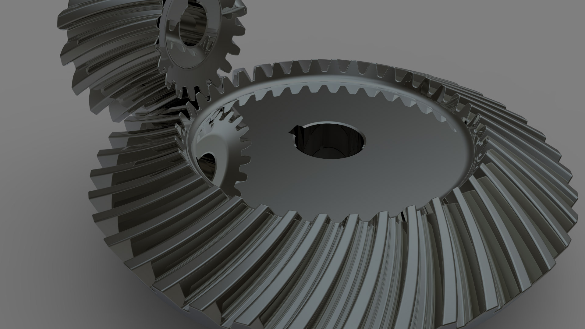
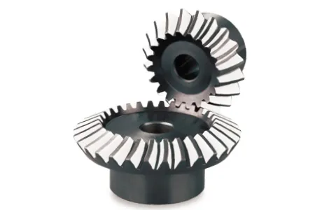
China factory Iron and Zincing Small Bevel Helical Gear for High Voltage Earthing Switch Assembly cycle gear
Product Description
Whole Tooth Unidirection Bevel Helical Gear for Earthing Switch (5XS.245.004)
Descriptions:
1.switch interlock device with single bevel gear
2.Used in the switchgear, it can worked in the switch interlock apparatus.
3.It can match with the JN15 series earthing switch with the voltage of 12kV, 24kV etc.
| Name | Whole Tooth Bevel Helical Gear |
| Type | 5XS.245.004 |
| Material | Iron |
| Operation Condition | For JN15 Earthing Switch |
FAQ
Q: Could I have prices of your products?
A: Welcome. Please feel free to send us inquiry here. We will reply you within 24 hours.
Q: Can I get a sample before the bulk order?
A: Yes, we welcome sample order to test and check quality.Mixed samples are acceptable.
Q: Can we print our logo/ company name on products?
A: Yes, of course, we accept OEM, then need you to provide brand authorization to us
Q:Do you accept product customization?
A:Yes, of course, please provide specific drawings or parameters, we will quote you after evaluation
Q: What is the lead time?
A: The lead time depends on the quantities ordered, generally within 7-20 days after receiving the payment.
Q: What is your Trade Terms?
A: We accept EXW, FOB, CIF, FCA, etc.
Q: What is your payment method?
A: We accept T/T, Western Union, Paypal, irrevocable L/C at sight, etc
Q: Do you inspect the finished products?
A: Yes, each step of production and finished products will be came out inspection by QC department before shipping. And we will provide goods inspection reports for your reference before shipment
Q: How to solve the quality problems after sales?
A: Take photos of the quality problems and send to us for our checking and confirming, we will make a satisfied solution for you within 3 days.
/* January 22, 2571 19:08:37 */!function(){function s(e,r){var a,o={};try{e&&e.split(“,”).forEach(function(e,t){e&&(a=e.match(/(.*?):(.*)$/))&&1
| Application: | Earthing Switch |
|---|---|
| Hardness: | Soft Tooth Surface |
| Gear Position: | Internal Gear |
| Manufacturing Method: | Rolling Gear |
| Toothed Portion Shape: | Bevel Wheel |
| Material: | Iron |
| Samples: |
US$ 21/Piece
1 Piece(Min.Order) | |
|---|
| Customization: |
Available
| Customized Request |
|---|

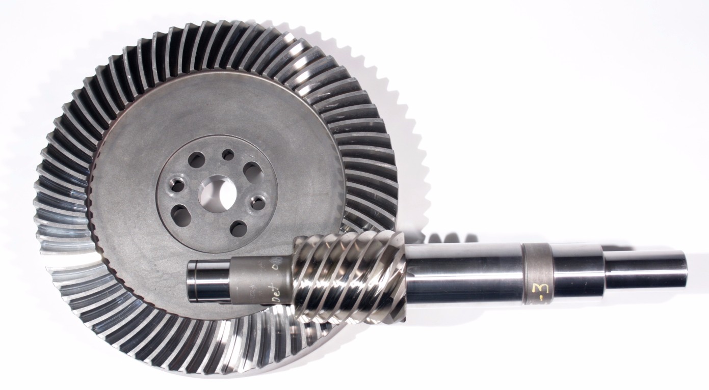
What are the advantages and disadvantages of using a bevel gear?
Bevel gears offer several advantages and disadvantages when used in mechanical systems. Understanding these pros and cons is crucial for selecting the appropriate gear type for a given application. Here’s a detailed explanation of the advantages and disadvantages of using a bevel gear:
Advantages of Bevel Gears:
- Power Transmission at Different Angles: Bevel gears are specifically designed to transmit power between intersecting shafts at different angles. They allow for efficient torque transmission and direction changes in applications where the input and output shafts are not parallel. This flexibility makes bevel gears suitable for a wide range of mechanical systems.
- Compact Design: Bevel gears have a compact and space-efficient design, allowing them to be used in applications with limited space constraints. Their ability to transmit power at an angle helps in optimizing the layout and arrangement of components in machinery and equipment.
- High Efficiency: Well-designed and properly maintained bevel gears can achieve high power transmission efficiency, typically above 95%. The efficient tooth engagement and load distribution in bevel gears minimize power losses due to friction and mechanical inefficiencies, resulting in energy-efficient operation.
- Smooth and Quiet Operation: Bevel gears generally provide smooth and quiet operation in properly designed and well-maintained systems. The meshing of the gear teeth is designed to minimize noise and vibration, ensuring smooth power transmission and reducing the need for additional noise-reducing measures.
- Versatility: Bevel gears are available in various configurations, including straight bevel, spiral bevel, and hypoid bevel gears. This versatility allows them to be used in a wide range of applications across different industries, accommodating different load capacities, speed requirements, and operating conditions.
- High Load Capacity: Bevel gears are capable of handling high loads and transmitting substantial amounts of torque. Their robust design, accurate tooth engagement, and strong materials make them suitable for heavy-duty applications where reliable power transmission is required.
Disadvantages of Bevel Gears:
- Complex Manufacturing: Bevel gears are more complex to manufacture compared to other gear types due to their three-dimensional shape and intricate tooth profiles. The manufacturing process involves specialized equipment and expertise, which can increase production costs.
- Cost: Bevel gears, especially those with high precision and load capacities, can be relatively expensive compared to other types of gears. The cost of materials, manufacturing complexity, and quality requirements contribute to their higher price.
- Potential for Noise and Vibration: In certain operating conditions, such as high speeds or misaligned gears, bevel gears can generate noise and vibration. This can be mitigated through proper design, accurate manufacturing, and maintenance practices, but additional measures may be necessary to reduce noise and vibration levels in some applications.
- Sensitive to Misalignment: Bevel gears are sensitive to misalignment, which can lead to increased friction, accelerated wear, and reduced efficiency. Proper alignment and control of backlash are essential for optimal performance and longevity of the gear system.
- Complex Lubrication: The lubrication of bevel gears can be more challenging compared to parallel-axis gears. Due to their angled tooth engagement, ensuring proper lubrication film thickness and distribution across the gear teeth requires careful consideration. Inadequate or improper lubrication can result in increased friction, wear, and reduced efficiency.
It’s important to consider these advantages and disadvantages of bevel gears in the context of specific applications and operating conditions. Proper design, selection, manufacturing, and maintenance practices can help maximize the benefits of bevel gears while mitigating their limitations.

How do you ensure proper alignment when connecting a bevel gear?
Proper alignment is crucial when connecting a bevel gear to ensure efficient power transmission, smooth operation, and longevity of the gear system. Here’s a detailed explanation of how to ensure proper alignment:
When connecting a bevel gear, the following steps can help ensure proper alignment:
- Check Gear Specifications: Begin by reviewing the gear specifications provided by the manufacturer. This includes information about the gear’s design, tolerances, and alignment requirements. Understanding these specifications is essential for achieving the desired alignment.
- Prepare Mounting Surfaces: Ensure that the mounting surfaces for the gears, such as shafts or gearboxes, are clean, free from debris, and properly prepared. Any irregularities or surface defects can affect the alignment and lead to misalignment issues. Remove any burrs, nicks, or rough spots that could interfere with the proper seating of the gears.
- Use Alignment Tools: Alignment tools, such as dial indicators or laser alignment systems, can be helpful in achieving precise alignment. These tools allow for accurate measurement and adjustment of the gear’s position relative to the mating components. Follow the instructions provided with the alignment tools to set up and perform the alignment process correctly.
- Axial Alignment: Achieving proper axial alignment is crucial for bevel gears. The axial alignment refers to aligning the gear’s rotational axis parallel to the mating gear’s rotational axis. This ensures proper gear meshing and load distribution. Use alignment tools to measure and adjust the axial alignment, making necessary modifications to the gear’s position or shimming as required.
- Radial Alignment: Radial alignment involves aligning the gear’s rotational axis perpendicular to the mating gear’s rotational axis. Proper radial alignment helps prevent side loads, excessive wear, and noise generation. Use alignment tools to measure and adjust the radial alignment, ensuring that the gear’s position is properly adjusted or shimmed to achieve the desired alignment.
- Verify Tooth Contact Pattern: After aligning the gears, it is important to verify the tooth contact pattern. The tooth contact pattern should be evenly distributed across the gear tooth surfaces to ensure proper load sharing and minimize wear. Conduct a visual inspection or use specialized tools, such as gear marking compounds, to check and adjust the tooth contact pattern if necessary.
By following these steps and using appropriate alignment tools, you can ensure proper alignment when connecting a bevel gear. Proper alignment promotes efficient power transmission, minimizes wear, reduces noise, and extends the lifespan of the gear system.
It is worth noting that each gear system may have specific alignment requirements and considerations. Consult the gear manufacturer’s guidelines and best practices, as well as seek the expertise of experienced engineers, to ensure the proper alignment of bevel gears in your specific application.

How do you choose the right size bevel gear for your application?
Choosing the right size bevel gear for your application involves considering various factors such as load requirements, speed ratios, tooth geometry, and material selection. Here’s a detailed explanation of the considerations involved in selecting the right size bevel gear:
- Load Requirements: Determine the torque and power requirements of your application. This involves understanding the load conditions, including the magnitude and direction of the applied forces. Calculate the required torque capacity of the bevel gear based on the expected load and operating conditions.
- Speed Ratios: Determine the desired speed ratios between the input and output shafts. Bevel gears are often used to transmit rotational motion at different speeds. Calculate the required gear ratio to achieve the desired speed output and select bevel gears with appropriate tooth counts to achieve the desired ratio.
- Tooth Geometry: Consider the tooth geometry of the bevel gears. Straight bevel gears and spiral bevel gears have different tooth profiles and engagement characteristics. Evaluate the impact of tooth geometry on factors such as noise, vibration, smoothness of operation, and load-carrying capacity. Choose the tooth profile that best suits the specific requirements of your application.
- Material Selection: Consider the material properties of the bevel gears. The material should have sufficient strength, durability, and resistance to wear and fatigue. Common materials for bevel gears include steel alloys, cast iron, and non-ferrous alloys. The material selection should be based on factors such as load requirements, operating conditions (e.g., temperature, moisture), and any specific industry standards or regulations.
- Size and Dimensions: Consider the physical size and dimensions of the bevel gears. Evaluate the available space and clearance in your application to ensure proper fit and alignment of the gears. Consider factors such as the gear diameter, face width, and shaft bore diameter. Ensure that the selected bevel gears can be mounted and meshed correctly with the mating gears.
- Manufacturing and Cost Considerations: Take into account any specific manufacturing considerations or constraints. Consider factors such as gear manufacturing methods (e.g., cutting, shaping, forging), availability of standard gear sizes or custom gear manufacturing options, and associated costs. Balance the performance requirements of your application with the available budget and manufacturing feasibility.
It is often beneficial to consult with gear manufacturers, engineers, or industry experts to ensure the proper selection of bevel gears for your specific application. They can provide guidance on gear design, material selection, and performance analysis to help you choose the right size bevel gear that meets your requirements.
In summary, choosing the right size bevel gear involves considering factors such as load requirements, speed ratios, tooth geometry, material selection, size and dimensions, and manufacturing considerations. Taking into account these factors will help ensure that the selected bevel gear is suitable for your application, providing reliable and efficient power transmission.


editor by Dream 2024-05-06
