China high quality Large Size Heavy Gear Ring, Girth Gear Auto Parts, CNC Machined Small Steel Rack and Pinion Gear top gear
Product Description
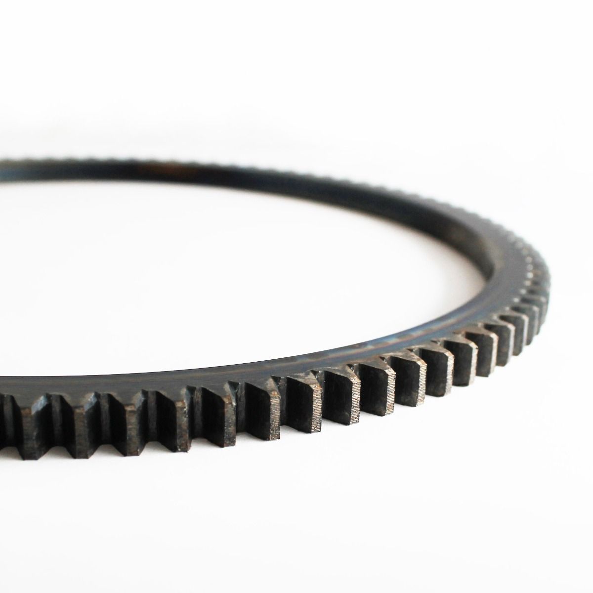
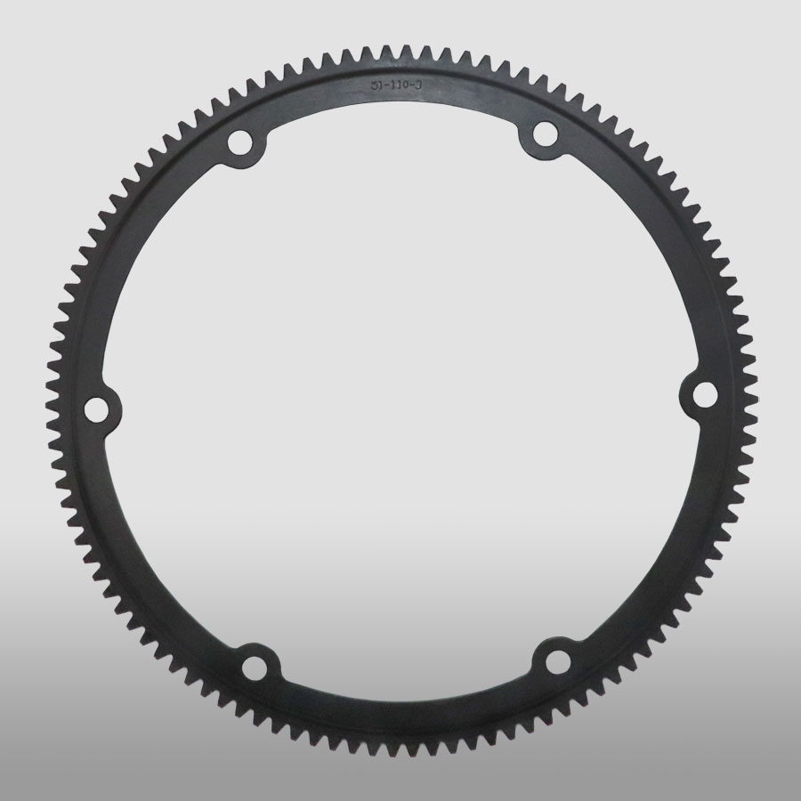
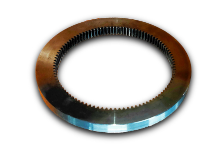
CNC Machined Small Steel Rack and Pinion Gear, Rack Gear
CITICHL Pinion Gear invested in significant resources and achieved many innovations with pinions. The right combination of material, hardness and finishing between pinion and gear is crucial for a long lifetime of the installed equipment. We design and manufacture pinions to match every customers need, no matter how unique the situation might be.
Casting & forging ability
CITICHL is the casting & forging center in central-south China, possessing 50t electric arc furnace, 60t LF ladle refining furnace, and 60t VD/VOD refining furnace, etc. We can pour 350t liquid steel 1 time and yields more than 200,000t of high quality liquid steel and can produce the high quality steel of more than 260 steel grades such as carbon steel, structural alloy steel and the structural steel, refractory steel and stainless steel of special requirement. The maximum weight of casting, gray casting, graphite cast iron and non-ferrous casting is 200t, 30t, 20t and 205t separately.
The company is the forging center in central-south China. It is very powerful in forging. The single free forging is 100t(max weight). We can roll rings of different sections of carbon steel, alloy steel, high temperature alloy and non-ferrous alloys such as copper alloy, aluminum alloy and titanium alloy. The maximum diameter is 5.5m and single piece of the forging weighs 10t. We have 8400t, 3150t, 1600t, water press and RAW 200/160-5000/750 large-size ring mill of high precision in Asia made in WAGNER, Germany.
Our pinion gears Features
Pinion design: bored CHINAMFG on shaft / integral self aligned spur, helical or double helical
forged alloyed steel
Spur, helical or double helical
Three different designs:Fabricated steel – forged ring – rolled plate
Standards/Certificates :• CHINAMFG EN ISO • AWS • ASTM • ASME • DIN
Pinion gear cutting machines
Φ16m CNC hobbing Machine
Φ12m Gear cutting machine (Switzerland)
Φ10m hobbing machine (Germany)
Φ4m CNC high speed hobbing machine (Germany)
Φ1.6m Horizontal CNC hobbing machine (Germany)
Φ5m CNC profile gear grinding machine (Germany)
Φ2.8m CNC Profile gear grinding machine (Germany)
Φ1.25m CNC Profile gear grinding machine (Germany)
Φ1m CNC Profile gear grinding machine (Germany)
Specifications of Gear :
| No. | Item | Description | |
| 1 | Diameter | ≤15m | |
| 2 | Module | ≤45 | |
| 3 | Material | Cast Alloy Steel, Cast Carbon Steel, Forged Alloy Steel, Forged Carbon Steel | |
| 4 | Structure From | Integrated, Half to Half, Four Pieces and More Pieces | |
| 5 | Heat Treatment | Quenching & Tempering, Normalizing & Tempering, Carburizing & Quenching & Tempering | |
| 6 | Tooth Form | Annular Gear, Outer Gear Ring | |
| 7 | Standard | ISO, EN, DIN, AISI, ASTM, JIS, IS, GB |
Inspection and Test Outline of Girth Gear:
| No. | Item | Inspection Area | Acceptance Criteria | Inspection Stage | Certificates |
| 1 | Chemical Composition |
Sample | Material Requirement | When Smelting After Heat Treatment |
Chemical Composition Report |
| 2 | Mechanical Properties |
Sample(Test Bar on the Gear Body) | Technical Requirement | After Heat Treatment | Mechanical Properties Report |
| 3 | Heat Treatment |
Whole Body | Manufacturing Standard | During Heat Treatment | Heat Treatment Report Curves of Heat Treatment |
| 4 | Hardness Test |
Tooth Surface, 3 Points Per 90° | Technical Requirement | After Heat Treatment | Hardness Teat Report |
| After Semi Finish Machining |
|||||
| 5 | Dimension Inspection |
Whole Body | Drawing | After Semi Finish Machining |
Dimension Inspection Report |
| Finish Machining | |||||
| 6 | Magnetic Power Test (MT) | Tooth Surface | Agreed Standard | After Finish Gear Hobbing |
MT Report |
| 7 | UT | Spokes Parts | Agreed Standard | After Rough Machining | UT Report |
| After Welded | |||||
| After Semi Finish Machining |
|||||
| 8 | PT | Defect Area | No Defect Indicated | After Digging After Welded |
PT Record |
| 9 | Mark Inspection | Whole Body | Manufacturing Standard | Final Inspection | Pictures |
| 10 | Appearance Inspection |
Whole Body | CIC’s Requirement | Before Packing (Final Inspection) |
|
| 11 | Anti-rust Inspection |
Whole Body | Agreed Anti-rust Agent | Before Packing | Pictures |
| 12 | Packing Inspection |
Whole Body | Agreed Packing Form | During Packing | Pictures |
Facilities For Manufacturing Gear ring:
| No. | Item | Description |
| 1 | Smelting & Casting Capability | 40t ,50t, 80t Series AC Electric Arc Furnace 2×150t, 60t LF Ladle Refining Furnace 150t, 60t Series VD/VOD Furnace 20×18m Large Pouring Facility We can pour 900t refining liquid steel one time, and achieve vacuum poured 600t steel ingots. We can produce the high quality steel of more than 260 steel grades as carbon steel,structural alloy steel and the structural steel, refractory steel and stainless steel of special requirement. The maximum weight of casting steel, gray casting, graphite cast iron and non-ferrous casting is 600t, 200t, 150t and 20t separately. |
| 2 | Forging Capability | The only one in the word, the most technologically advanced and the largest specification18500t Oil Press, equipped with 750t.m forging operation machine 8400t Water Press 3150t Water Press 1600t Water Press Φ5m High Precision Ring Mill ( WAGNER,Germany) Φ12m High Precision Ring Mill We can roll rings of different sections of carbon steel, alloy steel, high temperature alloy steel and non-ferrous alloys such as copper alloy, aluminum alloy and titanium alloy. Max. Diameter of rolled ring will be 12m. |
| 3 | Heat Treatment Capability | 9×9×15m,8×8×12m,6×6×15m,15×16×6.5m,16×20×6m ,7×7×17m Series Heat Furnace and Heat Treatment Furnaces φ2.0×30m,φ3.0×5.0m Series Heat Treatment Furnaces φ5.0×2.5m,φ3.2×1.5m,φ3.0×5.0m,φ2.0×5m Series Carburizing Furnaces & Nitriding Furnaces & Quenching Bathes φ2.0×30m Well Type CNC Electrical Furnaces Φ3.0×5.0M Horizontal Gas Temperature-differential Furnace Double-frequency and Double-position Quenching Lathe of Pinion Shaft |
| 4 | Machining Capability | 1. ≥5m CNC Heavy Duty Vertical Lathes 12m CNC Double-column Vertical Lathe 10m CNC Double-column Vertical Lathe 10m CNC Single-column Vertical Lathe 6.3m Heavy Duty Vertical Lathe 5m CNC Heavy Duty Vertical Lathe |
| 2. ≥5m Vertical Gear Hobbing Machines 15m CNC Vertical Gear Hobbing Machine 10m Gear Hobbing Machine 8m Gear Hobbing Machine 5m Gear Hobbing Machine 3m Gear Hobbing Machining |
||
| 3. Imported High-precision Gear Grinding Machines 0.8m~3.5m CNC Molding Gear Grinding Machines |
||
| 4. Large Boring & Milling Machines 220 CNC Floor-mounted Boring & Milling Machine 200 CNC Floor-mounted Boring & Milling Machine 160 CNC Floor-mounted Boring & Milling Machine |
/* January 22, 2571 19:08:37 */!function(){function s(e,r){var a,o={};try{e&&e.split(“,”).forEach(function(e,t){e&&(a=e.match(/(.*?):(.*)$/))&&1
| Application: | Machinery, Marine |
|---|---|
| Hardness: | as Requirement |
| Gear Position: | External Gear |
| Manufacturing Method: | Cut Gear |
| Toothed Portion Shape: | Bevel Wheel |
| Material: | Cast Steel |
| Customization: |
Available
| Customized Request |
|---|
How do you install a ring gear system?
Installing a ring gear system requires careful attention to ensure proper alignment, engagement, and secure attachment. Here’s a detailed explanation of the installation process:
- Prepare the Components: Gather all the necessary components for the ring gear system installation, including the ring gear, driving gear, and any other associated gears or components.
- Clean the Surfaces: Thoroughly clean the mounting surfaces of the gears and the mating components to remove any dirt, debris, or old lubricant. Clean surfaces will ensure better engagement and prevent contamination of the gear system.
- Inspect the Gears: Carefully inspect the ring gear and other gears for any signs of damage, wear, or misalignment. Check the teeth for any chips, cracks, or irregularities that may affect the performance of the gear system. Replace any damaged or worn gears before proceeding with the installation.
- Ensure Proper Alignment: Align the ring gear and the driving gear in the desired configuration. The alignment depends on the specific gear system and application requirements. Follow the manufacturer’s guidelines or engineering specifications to achieve the correct alignment.
- Establish Gear Engagement: Position the driving gear in close proximity to the ring gear and ensure proper engagement of the gear teeth. The teeth should mesh smoothly and evenly without any gaps or interference. Adjust the positioning of the gears if necessary to achieve optimal engagement.
- Secure Attachment: Once the gears are properly aligned and engaged, secure the ring gear in place. This may involve bolting or fastening the ring gear to a stationary component or housing. Follow the recommended torque specifications provided by the manufacturer to ensure proper tightening without overloading the gear system.
- Check Clearance and Backlash: Verify that there is adequate clearance between the gears and other nearby components to prevent interference during operation. Also, check the backlash, which is the slight gap between the meshing teeth, to ensure it falls within the recommended range. Adjust the gear positioning if clearance or backlash is outside the acceptable limits.
- Apply Lubrication: Apply the appropriate lubricant to the gear teeth and the mating surfaces to reduce friction and wear. Refer to the manufacturer’s recommendations for the type and amount of lubricant to use. Proper lubrication is crucial for smooth gear operation and longevity.
- Perform Function and Safety Tests: After the installation, perform function tests to ensure the gear system operates smoothly and without any abnormal noise or vibration. Additionally, check for any safety considerations, such as the presence of appropriate guards or protective covers if required for the specific application.
It’s important to note that the installation process may vary depending on the specific gear system, machinery, and manufacturer’s guidelines. Always refer to the provided instructions and consult with experts or professionals if needed to ensure a proper and accurate installation of the ring gear system.
Are ring gears suitable for high-torque applications?
Ring gears are indeed suitable for high-torque applications. Here’s a detailed explanation of why ring gears are suitable for high-torque applications:
Ring gears are designed to handle high torque loads and are commonly used in various applications that require substantial torque transmission. Here are the reasons why ring gears are well-suited for high-torque applications:
- Robust Construction: Ring gears are typically constructed with robust materials, such as hardened steel or other high-strength alloys. This construction provides the necessary strength, durability, and resistance to withstand high torque forces without deformation or failure.
- Large Contact Area: Ring gears have a large contact area between their gear teeth, which allows for efficient power transmission and load distribution. The larger contact area enables the ring gear to transmit higher torque without experiencing excessive stress concentrations or localized overloading.
- Optimized Tooth Geometry: The tooth geometry of ring gears is designed to handle high torque. The shape and profile of the gear teeth are optimized to distribute the torque load evenly, minimizing stress concentrations and enhancing the gear’s ability to transmit higher torque without premature wear or failure.
- Multiple Gear Engagements: Ring gears often engage with multiple gears or pinions, which further enhances their torque capacity. The engagement of multiple gears allows for load sharing, distributing the torque across multiple contact points and reducing the strain on individual gear teeth.
- Customizable Gear Ratios: Ring gears can be designed with various gear ratios to meet specific torque requirements. By adjusting the tooth count or diameter of the ring gear and mating gears, the gear system can be optimized for high torque applications while maintaining the desired speed or rotational characteristics.
- Used in Heavy-Duty Applications: Ring gears are widely used in heavy-duty applications that demand high torque transmission. Examples include automotive differentials, industrial gearboxes, mining equipment, construction machinery, and wind turbines. These applications rely on ring gears to effectively transmit and handle the high torque generated by powerful engines, motors, or turbines.
It’s important to note that while ring gears are suitable for high-torque applications, proper engineering analysis and selection should be carried out to ensure that the specific design, material, and size of the ring gear are appropriate for the intended torque requirements. Factors such as gear tooth strength, gear geometry, material properties, lubrication, and operating conditions should be carefully considered to ensure reliable and efficient performance in high-torque applications.
What are the applications of ring gears?
Ring gears, also known as annular gears or internal gears, have a wide range of applications across various industries and mechanical systems. Here’s a detailed explanation of the applications of ring gears:
Ring gears are commonly used in numerous applications where rotational motion, torque transmission, and load distribution are essential. The unique design and characteristics of ring gears make them suitable for a variety of mechanical systems. Here are some common applications of ring gears:
- Automotive Transmissions: Ring gears are extensively used in automotive transmissions, particularly in automatic and manual transmissions. They are part of the gear train that transfers rotational motion and torque from the engine to the wheels. Ring gears in automotive applications are typically large in size and designed to handle high torque loads.
- Differential Systems: Ring gears play a crucial role in differential systems found in vehicles. The differential assembly allows the wheels on an axle to rotate at different speeds while distributing torque evenly. Ring gears form an integral part of the differential assembly, enabling torque transfer and speed differentiation between the drive wheels.
- Planetary Gear Systems: Ring gears are a fundamental component in planetary gear systems, which are widely used in various applications. Planetary gear systems consist of a central sun gear, planet gears, and a ring gear. The ring gear serves as the outer ring that meshes with the planet gears and the sun gear. Planetary gear systems offer high gear ratios, compactness, and versatility, making them suitable for applications such as automotive transmissions, industrial machinery, and aerospace systems.
- Industrial Machinery: Ring gears find extensive use in industrial machinery for power transmission, motion control, and speed regulation. They are employed in equipment such as gearboxes, speed reducers, hoists, conveyors, and rotary tables. Ring gears enable efficient torque transmission, precise motion control, and load distribution in these industrial applications.
- Robotics and Automation: Ring gears are utilized in robotics and automation systems for precise motion control and synchronization. They can be found in robotic arms, automated assembly lines, CNC machines, and other robotic applications where accurate positioning and precise motion are critical. Ring gears provide the necessary torque transmission and gear reduction required for precise robotic movements.
- Power Generation: Ring gears are used in power generation equipment, such as wind turbines and hydroelectric generators. They form part of the gearboxes that convert the rotational motion of the turbine or generator rotor into electrical energy. Ring gears in power generation applications need to handle high torque loads, operate reliably, and provide efficient power transmission.
- Heavy Machinery and Construction Equipment: Ring gears are employed in heavy machinery and construction equipment, including excavators, cranes, mining equipment, and agricultural machinery. They facilitate the transmission of power and torque for various functions, such as lifting, digging, and material handling. Ring gears in these applications are designed to withstand high loads, rugged environments, and demanding operating conditions.
These are just a few examples of the applications of ring gears. Their versatility, load-carrying capacity, compact design, and ability to achieve high gear ratios make them suitable for a wide range of mechanical systems across industries.
The specific design, size, and material selection of ring gears may vary depending on the application requirements, operating conditions, and performance specifications.


editor by CX 2024-04-10