China Hot selling Diameter 15m Girth Bevel Gear for Rotary Kiln and Ball Mill supplier
Product Description
Product Description
Factory price large Cast Steel, Iron Kiln Girth Gear for ball mill
Casting & forging ability
CITICHL is the casting & forging center in central-south China, possessing 50t electric arc furnace, 60t LF ladle refining furnace, and 60t VD/VOD refining furnace, etc. We can pour 350t liquid steel 1 time and yields more than 200,000t of high quality liquid steel and can produce the high quality steel of more than 260 steel grades such as carbon steel, structural alloy steel and the structural steel, refractory steel and stainless steel of special requirement. The maximum weight of casting, gray casting, graphite cast iron and non-ferrous casting is 200t, 30t, 20t and 205t separately.
The company is the forging center in central-south China. It is very powerful in forging. The single free forging is 100t(max weight). We can roll rings of different sections of carbon steel, alloy steel, high temperature alloy and non-ferrous alloys such as copper alloy, aluminum alloy and titanium alloy. The maximum diameter is 5.5m and single piece of the forging weighs 10t. We have 8400t, 3150t, 1600t, water press and RAW 200/160-5000/750 large-size ring mill of high precision in Asia made in WAGNER, Germany.
Our girth gears Features
Module Range: 10 Module to 70 Module.
Diameter : Min 800mm to16000 mm.
Weight : Max 120 MT single piece.
Three different designs: Fabricated steel – forged ring – rolled plate
Standards/Certificates :• CHINAMFG EN ISO • AWS • ASTM • ASME • DIN
Girth gear cutting machines
Φ16m CNC hobbing Machine
Φ12m Gear cutting machine (Switzerland)
Φ10m hobbing machine (Germany)
Φ4m CNC high speed hobbing machine (Germany)
Φ1.6m Horizontal CNC hobbing machine (Germany)
Φ5m CNC profile gear grinding machine (Germany)
Φ2.8m CNC Profile gear grinding machine (Germany)
Φ1.25m CNC Profile gear grinding machine (Germany)
Φ1m CNC Profile gear grinding machine (Germany)
Specifications of Gear :
| No. | Item | Description | |
| 1 | Diameter | ≤15m | |
| 2 | Module | ≤45 | |
| 3 | Material | Cast Alloy Steel, Cast Carbon Steel, Forged Alloy Steel, Forged Carbon Steel | |
| 4 | Structure From | Integrated, Half to Half, Four Pieces and More Pieces | |
| 5 | Heat Treatment | Quenching & Tempering, Normalizing & Tempering, Carburizing & Quenching & Tempering | |
| 6 | Tooth Form | Annular Gear, Outer Gear Ring | |
| 7 | Standard | ISO, EN, DIN, AISI, ASTM, JIS, IS, GB |
Inspection and Test Outline of Girth Gear:
| No. | Item | Inspection Area | Acceptance Criteria | Inspection Stage | Certificates |
| 1 | Chemical Composition |
Sample | Material Requirement | When Smelting After Heat Treatment |
Chemical Composition Report |
| 2 | Mechanical Properties |
Sample(Test Bar on the Gear Body) | Technical Requirement | After Heat Treatment | Mechanical Properties Report |
| 3 | Heat Treatment |
Whole Body | Manufacturing Standard | During Heat Treatment | Heat Treatment Report Curves of Heat Treatment |
| 4 | Hardness Test |
Tooth Surface, 3 Points Per 90° | Technical Requirement | After Heat Treatment | Hardness Teat Report |
| After Semi Finish Machining |
|||||
| 5 | Dimension Inspection |
Whole Body | Drawing | After Semi Finish Machining |
Dimension Inspection Report |
| Finish Machining | |||||
| 6 | Magnetic Power Test (MT) | Tooth Surface | Agreed Standard | After Finish Gear Hobbing |
MT Report |
| 7 | UT | Spokes Parts | Agreed Standard | After Rough Machining | UT Report |
| After Welded | |||||
| After Semi Finish Machining |
|||||
| 8 | PT | Defect Area | No Defect Indicated | After Digging After Welded |
PT Record |
| 9 | Mark Inspection | Whole Body | Manufacturing Standard | Final Inspection | Pictures |
| 10 | Appearance Inspection |
Whole Body | CIC’s Requirement | Before Packing (Final Inspection) |
|
| 11 | Anti-rust Inspection |
Whole Body | Agreed Anti-rust Agent | Before Packing | Pictures |
| 12 | Packing Inspection |
Whole Body | Agreed Packing Form | During Packing | Pictures |
Facilities For Manufacturing Gear ring:
| No. | Item | Description |
| 1 | Smelting & Casting Capability | 40t ,50t, 80t Series AC Electric Arc Furnace 2×150t, 60t LF Ladle Refining Furnace 150t, 60t Series VD/VOD Furnace 20×18m Large Pouring Facility We can pour 900t refining liquid steel one time, and achieve vacuum poured 600t steel ingots. We can produce the high quality steel of more than 260 steel grades as carbon steel,structural alloy steel and the structural steel, refractory steel and stainless steel of special requirement. The maximum weight of casting steel, gray casting, graphite cast iron and non-ferrous casting is 600t, 200t, 150t and 20t separately. |
| 2 | Forging Capability | The only one in the word, the most technologically advanced and the largest specification18500t Oil Press, equipped with 750t.m forging operation machine 8400t Water Press 3150t Water Press 1600t Water Press Φ5m High Precision Ring Mill ( WAGNER,Germany) Φ12m High Precision Ring Mill We can roll rings of different sections of carbon steel, alloy steel, high temperature alloy steel and non-ferrous alloys such as copper alloy, aluminum alloy and titanium alloy. Max. Diameter of rolled ring will be 12m. |
| 3 | Heat Treatment Capability | 9×9×15m,8×8×12m,6×6×15m,15×16×6.5m,16×20×6m ,7×7×17m Series Heat Furnace and Heat Treatment Furnaces φ2.0×30m,φ3.0×5.0m Series Heat Treatment Furnaces φ5.0×2.5m,φ3.2×1.5m,φ3.0×5.0m,φ2.0×5m Series Carburizing Furnaces & Nitriding Furnaces & Quenching Bathes φ2.0×30m Well Type CNC Electrical Furnaces Φ3.0×5.0M Horizontal Gas Temperature-differential Furnace Double-frequency and Double-position Quenching Lathe of Pinion Shaft |
| 4 | Machining Capability | 1. ≥5m CNC Heavy Duty Vertical Lathes 12m CNC Double-column Vertical Lathe 10m CNC Double-column Vertical Lathe 10m CNC Single-column Vertical Lathe 6.3m Heavy Duty Vertical Lathe 5m CNC Heavy Duty Vertical Lathe |
| 2. ≥5m Vertical Gear Hobbing Machines 15m CNC Vertical Gear Hobbing Machine 10m Gear Hobbing Machine 8m Gear Hobbing Machine 5m Gear Hobbing Machine 3m Gear Hobbing Machining |
||
| 3. Imported High-precision Gear Grinding Machines 0.8m~3.5m CNC Molding Gear Grinding Machines |
||
| 4. Large Boring & Milling Machines 220 CNC Floor-mounted Boring & Milling Machine 200 CNC Floor-mounted Boring & Milling Machine 160 CNC Floor-mounted Boring & Milling Machine |
/* March 10, 2571 17:59:20 */!function(){function s(e,r){var a,o={};try{e&&e.split(“,”).forEach(function(e,t){e&&(a=e.match(/(.*?):(.*)$/))&&1
| Application: | Industry |
|---|---|
| Hardness: | According to Customer′s Requirement |
| Gear Position: | External Gear |
| Manufacturing Method: | Cast Gear |
| Toothed Portion Shape: | Spur Gear |
| Material: | Steel |
| Customization: |
Available
| Customized Request |
|---|
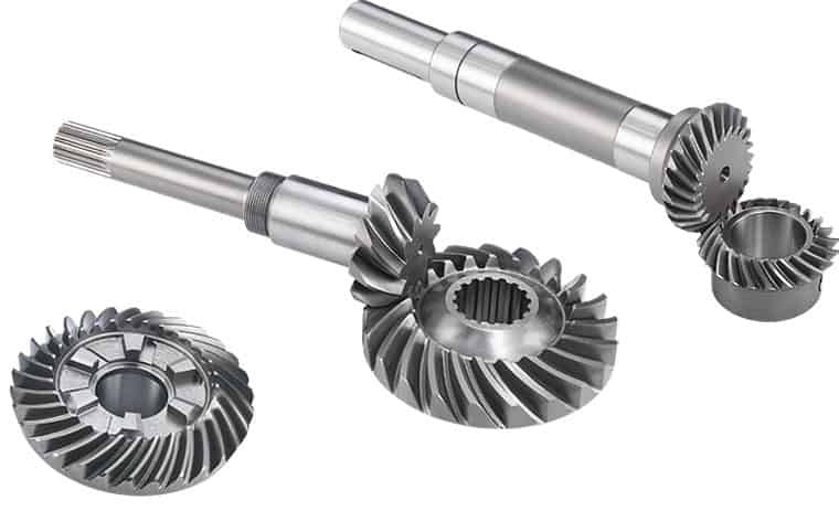
How does a bevel gear impact the overall efficiency of a system?
A bevel gear plays a significant role in determining the overall efficiency of a system. Its design, quality, and operating conditions can impact the efficiency of power transmission and the system as a whole. Here’s a detailed explanation of how a bevel gear can impact overall efficiency:
- Power Transmission Efficiency: The primary function of a bevel gear is to transmit power between intersecting shafts at different angles. The efficiency of power transmission through a bevel gear depends on factors such as gear geometry, tooth profile, material quality, lubrication, and operating conditions. In an ideally designed and well-maintained system, bevel gears can achieve high power transmission efficiency, typically above 95%. However, factors such as friction, misalignment, inadequate lubrication, and gear tooth wear can reduce efficiency and result in power losses.
- Friction and Mechanical Losses: Bevel gears experience friction between their mating teeth during operation. This friction generates heat and causes mechanical losses, reducing the overall efficiency of the system. Factors that affect friction and mechanical losses include the gear tooth profile, surface finish, lubrication quality, and operating conditions. High-quality gears with well-designed tooth profiles, proper lubrication, and optimized operating conditions can minimize friction and mechanical losses, improving the overall efficiency.
- Gear Tooth Design: The design of the bevel gear tooth profile influences its efficiency. Factors such as tooth shape, size, pressure angle, and tooth contact pattern affect the load distribution, friction, and efficiency. Proper tooth design, including optimized tooth profiles and contact patterns, help distribute the load evenly and minimize sliding between the teeth. Well-designed bevel gears with accurate tooth profiles can achieve higher efficiency by reducing friction and wear.
- Material Quality and Manufacturing Precision: The material quality and manufacturing precision of bevel gears impact their durability, smooth operation, and efficiency. High-quality materials with suitable hardness, strength, and wear resistance can minimize friction, wear, and power losses. Additionally, precise manufacturing processes ensure accurate gear geometry, tooth engagement, and alignment, optimizing the efficiency of power transmission and reducing losses due to misalignment or backlash.
- Lubrication and Wear: Proper lubrication is crucial for reducing friction, wear, and power losses in bevel gears. Insufficient or degraded lubrication can lead to metal-to-metal contact, increased friction, and accelerated wear, resulting in reduced efficiency. Adequate lubrication with the recommended lubricant type, viscosity, and replenishment schedule ensures a sufficient lubricating film between the gear teeth, minimizing friction and wear and improving overall efficiency.
- Misalignment and Backlash: Misalignment and excessive backlash in bevel gears can negatively impact efficiency. Misalignment causes uneven loading, increased friction, and accelerated wear. Excessive backlash results in power losses during direction changes and can lead to impact loads and vibration. Proper alignment and control of backlash within acceptable limits are crucial for maintaining high efficiency in a bevel gear system.
Overall, a well-designed bevel gear system with high-quality materials, accurate manufacturing, proper lubrication, and minimal losses due to friction, misalignment, or wear can achieve high efficiency in power transmission. Regular maintenance, monitoring, and optimization of operating conditions are essential to preserve the efficiency of the system over time.
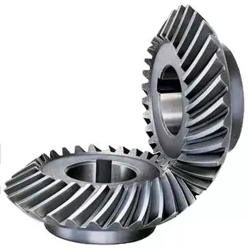
Can bevel gears be used in automotive applications?
Yes, bevel gears can be used in automotive applications due to their unique characteristics and ability to transmit power between intersecting shafts at different angles. Here’s a detailed explanation:
Bevel gears are commonly found in various automotive systems and components, offering several advantages for specific applications. Here are some key automotive applications where bevel gears are utilized:
- Differential: One of the primary applications of bevel gears in automotive systems is in the differential mechanism. The differential is responsible for distributing torque between the drive wheels while allowing them to rotate at different speeds, especially during cornering. Bevel gears, specifically hypoid gears, are used in the differential to transfer power from the driveshaft to the wheel axles at right angles. The compact size and high torque transmission capability of bevel gears make them suitable for this critical drivetrain component.
- Power Transfer: Bevel gears are utilized in automotive power transfer systems, such as transfer cases and drivelines. Transfer cases, commonly found in four-wheel drive (4WD) and all-wheel drive (AWD) vehicles, transfer power from the transmission to the front and rear axles. Bevel gears enable the necessary change in direction and torque transmission between the input and output shafts of the transfer case. Similarly, bevel gears can be used in drivelines to transfer power between differentials or between the transmission and the axles.
- Steering Systems: Bevel gears play a role in automotive steering systems, particularly in rack-and-pinion steering mechanisms. In these systems, bevel gears are used to convert the rotational motion of the steering wheel into the linear motion required for steering. Bevel gears help change the direction of motion, enabling the driver to control the vehicle’s steering angle. The compact size and precise motion transmission characteristics of bevel gears make them suitable for these steering applications.
- Auxiliary Systems: Bevel gears find application in various auxiliary automotive systems. For example, they can be used in engine timing systems to drive camshafts and synchronize valve operation. Bevel gears can also be employed in automotive differentials with limited-slip or locking capabilities, enhancing traction and vehicle stability in challenging road conditions. Additionally, they can be found in power seat adjusters, sunroof mechanisms, and other vehicle systems where torque transmission at different angles is required.
Bevel gears used in automotive applications are typically designed to withstand high loads, operate with minimal noise and vibration, and provide reliable power transmission. They are often manufactured from durable materials, such as alloy steels, and undergo heat treatment processes to enhance their strength and wear resistance.
It is important to note that the specific design and selection of bevel gears for automotive applications depend on factors such as torque requirements, space limitations, operating conditions, and cost considerations. Gear engineers and automotive manufacturers carefully consider these factors to ensure optimal performance, efficiency, and reliability in automotive systems.
In summary, bevel gears are extensively used in automotive applications, including differentials, power transfer systems, steering mechanisms, and auxiliary systems. Their ability to transmit power at varying angles, compact size, and robust construction make them well-suited for the demanding requirements of the automotive industry.
Are there different types of bevel gears available?
Yes, there are different types of bevel gears available to suit various applications and requirements. Here’s a detailed explanation of the different types of bevel gears:
- Straight Bevel Gears: Straight bevel gears are the most basic type of bevel gears. They have straight-cut teeth that are machined on the cone-shaped surface of the gears. The teeth of straight bevel gears are parallel to the gear axis and intersect at a 90-degree angle. These gears are commonly used when the intersecting shafts need to transmit rotational motion at a right angle.
- Spiral Bevel Gears: Spiral bevel gears are designed with curved teeth that are machined on the cone-shaped surface of the gears. The teeth of spiral bevel gears are cut in a spiral pattern, gradually curving along the gear surface. This spiral tooth geometry provides several advantages over straight bevel gears, including smoother engagement, reduced noise and vibration, and higher load-carrying capacity. Spiral bevel gears are commonly used in applications that require smooth and quiet operation, such as automotive rear axle drives, machine tools, and industrial machinery.
- Hypoid Bevel Gears: Hypoid bevel gears are similar to spiral bevel gears but have offset axes. The axes of hypoid bevel gears do not intersect and are non-parallel, allowing them to transmit rotational motion between shafts that are not in a straight line. Hypoid bevel gears are commonly used in applications where space constraints or specific shaft arrangements require a change in direction and torque transmission. They are often found in automotive drivetrains, power tools, and heavy machinery.
- Straight and Spiral Zerol Bevel Gears: Zerol bevel gears are similar to their straight and spiral counterparts but have a unique tooth profile. The teeth of zerol bevel gears are curved, similar to spiral bevel gears, but with a smaller spiral angle. This results in a tooth profile that is closer to a straight bevel gear. Straight and spiral zerol bevel gears provide a combination of the advantages of both straight and spiral bevel gears, including smoother engagement, reduced noise, and higher load-carrying capacity.
- Straight and Spiral Miter Gears: Miter gears, also known as mitre gears, are a special type of bevel gears that have equal numbers of teeth and intersect at a 90-degree angle. They are often used when rotational motion needs to be transmitted at a right angle without a change in direction. Miter gears can be either straight or spiral, depending on the tooth geometry.
These are the commonly used types of bevel gears. Each type has its own advantages and applications. The selection of the appropriate type of bevel gear depends on factors such as the required angle of transmission, load capacity, noise and vibration considerations, and the specific requirements of the application.
In summary, different types of bevel gears, including straight bevel gears, spiral bevel gears, hypoid bevel gears, straight and spiral zerol bevel gears, and straight and spiral miter gears, are available to suit various applications and accommodate different shaft arrangements.


editor by CX 2024-01-10