China manufacturer Customized High Precision Spiral Angular Straight Bevel Gear Miter Gear Brass Plastic Wheels for Sale Helical Pinion Gears top gear
Product Description
Customized High Precision Spiral Angular straight Bevel Gear miter gear brass plastic wheels for sale helical pinion gears
| Process | CNC machining,CNC milling, cnc lathe machining |
| Available Material | 1.Stainless Steel: SS201, SS303, SS304, SS316, SS416, SS420,etc. |
| 2.Steel: C45, 40Cr, 42CrMo, 20CrNiMo, 20CrMnTi, etc. (AISI 1045, 5140, 4140/4142, 8620 etc.) | |
| 3. Brass:C36000 ( C26800), C37700 ( HPb59), C38500( HPb58), C27200CuZn37), C28000(CuZn40),etc. | |
| 4.Bronze: C51000, C52100, C54400, etc. | |
| 5. Iron: 1213, 12L14,1215,etc. | |
| 6. Aluminum: Al6061, Al6063,Al2571,Al7075 etc | |
| 7. Carbon steel:AISI1006,AISI1571,AISI1571,etc. | |
| 8.Nylon PA66,MC901,POM plastic ects | |
| Hardness | HRC50~55 |
| Quality Control | ISO9001 and ISO14001 |
| Dimension bore tolerances | -/+0.01mm |
| Quality standard | AGMA, JIS, DIN |
| Size/Color | Gears and parts dimensions are according to drawings from customer, and colors are customized |
| Surface treatment | black oxide,Zn-plated,ni-plated,tin-plated,chrome plated,passivated,sandblast and anodize,chromate,polish,electro painting,black anodize,plain,H.D.G,etc. |
| Dimensions Tolerance | ±0.01mm or more precise |
| Samples confirmation and approval | samples shipped for confirmation and shipping cost paid by customers |
| Package | Inner clear plastic bag/outside carton/wooden pallets/ or any other special package as per customer’s requirements. |
Click here for more details!
Customization process
Support Customized Gears from Customers’ drawings and samples and Various non-standard customization
1.Products Discussions
Customers send drawings oramples, and quote according to customers’ requirements.
2.Molds designing
Designing 3D drawings and optimizing the products.
3.Drawing confirmation
Sending the mold drawing tothe customers , and the customers CHINAMFG for confirmation.
4.Molds Construction
Manufacture molds accurately and accurately according to the drawings.
5.Moulds Inspection and Moulds Test
Detect various indicators of molds and optimization of inner cavities.
6.Sample Aprroval from Customer
Customers approve the samples and confirm them for bulk production.
7.Mass Production
Bulk production according to customers’s PO
8.PO Finished
Shipping to the customer andthe customers receive the gears.
If you need other customized requirements, please click here to contact us!
Related Products
Why Choose Us
We enthusiastically provide sincere and prompt service to our customers and establish sustainable business relationship with them.
100% Factory inspection, we are responsible for any problems subjected to malfunction in warranty period.
We Can Provide You:
- On-time Delivery with More Choice
- Product Solutions and Service
- Long Quality Guarantee
- Local Technical Support
- Fast Response to Customers’ Feedbacks in 24 hours
Also I would like to take this opportunity to give a brief introduction of our CHINAMFG company:
Our company is a famous manufacturer of agriculture gearbox,worm reduce gearbox, PTO shafts, Sprockets ,rollar chains, bevel gear, pulleys and racks in china.
We have exported many products to our customers all over the world, we have long-time experience and strong technology support.
You also can check our website to know for more details, if you need our products catalogue, please contact with us.
Company information
/* March 10, 2571 17:59:20 */!function(){function s(e,r){var a,o={};try{e&&e.split(“,”).forEach(function(e,t){e&&(a=e.match(/(.*?):(.*)$/))&&1
| Application: | Motor, Electric Cars, Motorcycle, Machinery, Marine, Toy, Agricultural Machinery, Car, Transmission Gearbox |
|---|---|
| Hardness: | Hardened Tooth Surface |
| Gear Position: | External Gear |
| Manufacturing Method: | Cast Gear |
| Toothed Portion Shape: | Bevel Wheel |
| Material: | Stainless Steel |
| Samples: |
US$ 999/Piece
1 Piece(Min.Order) | |
|---|
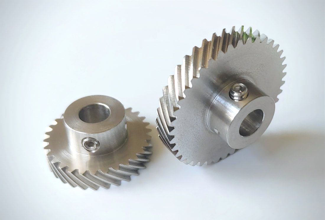
How do you install a helical gear system?
Installing a helical gear system involves several steps to ensure proper alignment, engagement, and smooth operation. Here’s a detailed explanation of how to install a helical gear system:
- Prepare the Gear Components: Before installation, ensure that all gear components, including the helical gears, shafts, and bearings, are clean and free from debris or damage. Inspect the gears for any signs of wear, pitting, or tooth damage that may affect their performance.
- Check Gear Specifications: Verify that the helical gears you are installing are the correct size, tooth profile, and helix angle for the intended application. Refer to the gear specifications and engineering drawings to ensure compatibility and proper gear meshing.
- Align the Shafts: Proper shaft alignment is crucial for the smooth operation of a helical gear system. Align the shafts accurately using precision alignment tools such as dial indicators or laser alignment systems. Align the shafts both radially and axially to minimize misalignment and ensure the gears mesh correctly.
- Install Bearings: Mount the appropriate bearings onto the shafts to support the helical gears. Ensure that the bearings are properly lubricated and securely mounted according to the manufacturer’s instructions. Proper bearing installation is essential for minimizing friction, supporting the gears, and maintaining the alignment of the gear system.
- Install the Gears: Carefully position the helical gears onto their respective shafts. Ensure that the gears are properly aligned and engage smoothly without any binding or interference. Use appropriate tools such as gear pullers or hydraulic presses, if necessary, to facilitate gear installation. Follow any specific instructions provided by the gear manufacturer for gear mounting.
- Check Gear Meshing: After the gears are installed, check the gear meshing to ensure proper engagement. Rotate the gears by hand or using a suitable drive system and observe the tooth contact pattern. The gear meshing should be uniform, with proper tooth engagement along the full width of the gear teeth. Adjust the gear position or shim thickness, if needed, to achieve the desired tooth contact pattern.
- Secure the Gears: Once the gear meshing is satisfactory, secure the helical gears in place using appropriate fasteners such as shaft collars, set screws, or retaining rings. Ensure that the fasteners are tightened to the specified torque values but avoid over-tightening, which can lead to excessive bearing load or gear distortion.
- Provide Lubrication: Apply the recommended lubricant to the gear teeth and bearings according to the gear manufacturer’s instructions. Proper lubrication is crucial for reducing friction, dissipating heat, and extending the gear system’s service life. Regularly monitor the lubrication levels and replenish or replace the lubricant as needed.
- Perform Initial Testing: After installation, perform an initial test run of the helical gear system. Gradually increase the speed and load to ensure smooth operation and proper gear performance. Monitor for any unusual noise, vibration, or overheating, which may indicate misalignment, inadequate lubrication, or other issues that require adjustment or further inspection.
It’s important to note that the installation process may vary depending on the specific gear system, application, and manufacturer recommendations. Always refer to the gear manufacturer’s instructions and consult with experienced professionals or engineers when in doubt. Proper installation and maintenance are crucial for the optimal performance and longevity of a helical gear system.
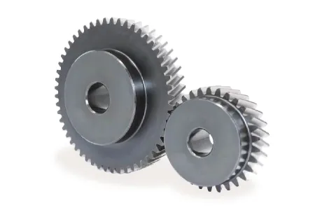
What are the environmental considerations when using helical gears?
When using helical gears, several environmental considerations should be taken into account. These considerations primarily focus on reducing the environmental impact associated with gear manufacturing, operation, and maintenance. Here is a detailed explanation of the environmental considerations when using helical gears:
- Material Selection: The choice of materials for helical gears can have an environmental impact. Opting for materials that are recyclable, have a low carbon footprint, or are sourced from sustainable and responsible suppliers can help minimize the environmental footprint of gear production.
- Energy Efficiency: Helical gears can contribute to energy efficiency in machinery and equipment. By using helical gears with high efficiency, the overall energy consumption can be reduced, resulting in lower greenhouse gas emissions and energy-related environmental impacts.
- Lubrication: Proper lubrication of helical gears is essential for efficient operation and reducing wear. Choosing environmentally friendly lubricants, such as biodegradable or low-toxicity options, can minimize the potential harm to the environment in case of leakage or disposal.
- Maintenance and Inspection: Regular maintenance and inspection of helical gears can help identify and address issues such as misalignment, excessive wear, or inadequate lubrication. Promptly addressing these issues can extend the gear’s lifespan, reduce the need for replacements, and reduce waste generation.
- Noise and Vibration: Helical gears are known for their smooth operation, which helps reduce noise and vibration. This can have environmental benefits by minimizing noise pollution and creating a more comfortable and sustainable working environment.
- End-of-Life Considerations: When helical gears reach the end of their useful life, proper disposal or recycling practices should be followed. Recycling gears and their materials can help reduce waste and prevent the accumulation of non-biodegradable materials in landfills.
- Life Cycle Assessment: Conducting a life cycle assessment (LCA) of helical gears can provide a comprehensive evaluation of their environmental impact throughout their life cycle. This assessment considers factors such as raw material extraction, manufacturing processes, energy consumption, transportation, use phase, and end-of-life disposal. LCA can help identify areas for improvement and guide decision-making towards more sustainable gear solutions.
By considering these environmental factors when using helical gears, manufacturers and users can minimize the environmental impact associated with gear production, operation, and disposal. Implementing sustainable practices not only helps protect the environment but also promotes resource efficiency and long-term economic viability.
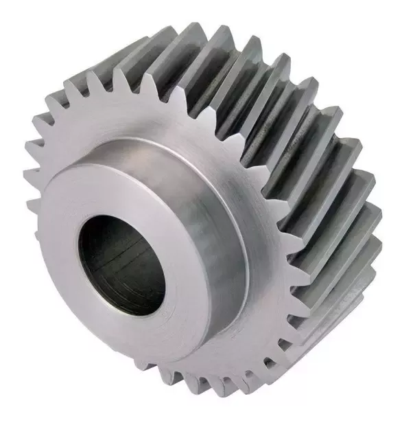
Can you explain the concept of helical gear teeth and their orientation?
The concept of helical gear teeth and their orientation is essential to understanding the design and operation of helical gears. Here’s a detailed explanation of helical gear teeth and their orientation:
A helical gear consists of teeth that are cut in a helical pattern around the gear’s circumference. Unlike spur gears, which have teeth that are perpendicular to the gear axis, helical gears have teeth that are angled or inclined with respect to the gear axis. This inclination gives the teeth a helix shape, resulting in the name “helical” gears.
The orientation of helical gear teeth is defined by two main parameters:
- Helix Angle: The helix angle represents the angle formed between the tooth surface and an imaginary line perpendicular to the gear axis. It determines the degree of inclination or spiral of the gear teeth. The helix angle is typically measured in degrees. Positive helix angles indicate a right-hand helix, where the teeth slope in a right-hand direction when viewed from the gear’s end. Negative helix angles represent a left-hand helix, where the teeth slope in a left-hand direction. The helix angle affects the gear’s performance characteristics, including tooth engagement, load distribution, and axial thrust.
- Lead Angle: The lead angle is the angle formed by the helical tooth and a plane perpendicular to the gear axis. It represents the angle of advance of the helix over one revolution of the gear. The lead angle is equal to the helix angle divided by the gear’s number of teeth. It is commonly used to define the helical gear’s size and pitch.
The helical tooth orientation offers several advantages over spur gears:
- Smooth and Quiet Operation: The helical shape of the teeth allows for gradual engagement and disengagement during gear rotation. This results in smoother and quieter operation compared to spur gears, which often produce noise due to the sudden contact between teeth.
- Increased Load-Carrying Capacity: The helical tooth design provides a larger contact area between meshing gears compared to spur gears. This increased contact area allows helical gears to transmit higher loads and handle greater torque without excessive wear or tooth failure.
- Load Distribution: The helical orientation of the teeth enables load distribution along the tooth face. Multiple teeth are engaged simultaneously, distributing the load across a broader surface area. This characteristic helps minimize stress concentrations and increases the gear’s durability.
- Axial Thrust Load: The helical tooth engagement introduces axial forces and thrust loads along the gear axis. These forces must be properly supported and managed in the gear system design to ensure smooth operation and prevent excessive wear or failure.
The design and manufacturing of helical gears require specialized cutting tools and machining processes. The helical teeth are typically generated using gear hobbing or gear shaping methods. The tooth profile is carefully designed to ensure proper meshing and minimize noise, vibration, and wear.
In summary, helical gear teeth have a helical or spiral shape, which distinguishes them from the perpendicular teeth of spur gears. The orientation of helical gear teeth is defined by the helix angle and lead angle. Helical gears offer advantages such as smooth operation, increased load-carrying capacity, load distribution, and axial thrust load. These characteristics make helical gears suitable for applications that require efficient power transmission, precise motion control, and reduced noise and vibration.


editor by CX 2023-12-25