China manufacturer High Precision Class 6~9, M 0.4~M 12 Spur Gear Bevel Gear, Helical Gear, gear ratio calculator
Product Description
High precision class 6~9, M 0.4~M 12 spur gear, bevel gear, helical gear,
Products description
|
Product Type |
M0.5~M12, Z8~80. standard gear, or according customer drawing to make. |
|
Material: |
Carbon Steel, Brass, Aluminium, Stainless steel, Plastic, POM, Delrin, Titanium Alloy etc. |
|
Process method |
CNC Turning, milling ,drilling, grinding etc. |
|
Surface finish: |
Chrome plating, Anodization, Powder coating, blackening, Sand blasting, Brushing & ploshing,Electrophoresis etc. |
|
OEM & ODM Service |
Available |
|
Design Software |
PRO/E, Auto CAD, Solid Works |
|
Trade Terms: |
FOB,,CIF,EXW |
|
Payment Terms: |
T/T, L/C, |
|
Packing: |
Foam, Carton, Standard Wooden boxes |
|
Capacity |
8,000~1,5000 pcs per month |
|
Delivery |
20-30 days after receiving PO |
|
Applications |
Automotive Parts,hydraulics, compressors,Industrial equipments, transmission parts, etc. |
|
Our services: |
CNC Machining, Milling, Stamping, Sheet metal fabricating, and Die-Casting |
Products show,
Our Company
Gear inspection
FAQ
Q1. What is your terms of packing?
A: Generally, we pack our goods in single color box. If you have special request about packing, pls negotiate with us in advance, we can pack the goods as your request.
Q2. What is your terms of payment?
A: T/T 30% as deposit, and 70% before delivery. We’ll show you the photos of the products and packages
before you pay the balance. Other payments terms, pls negotiate with us in advance, we can discuss.
Q3. What is your terms of delivery?
A: EXW, FOB, CFR, CIF.
Q4. How about your delivery time?
A: Generally, it will take 25 to 30 days after receiving your advance payment. The specific delivery time depends
on the items and the quantity of your order.
Q5. Can you produce according to the samples?
A: Yes, we can produce by your samples or technical drawings. We can build the molds and fixtures.
Q6. What is your sample policy?
A: We can supply the sample if we have ready parts in stock, but the customers have to pay the sample cost and
the courier cost.We welcome sample order.
Q7. Do you test all your goods before delivery?
A: Yes, we have 100% test before delivery
Q8: How do you make our business long-term and good relationship?
1. We keep good quality and competitive price to ensure our customers benefit ;
2. We respect every customer as our friend and we sincerely do business and make friends with them,
no matter where they come from.
/* March 10, 2571 17:59:20 */!function(){function s(e,r){var a,o={};try{e&&e.split(“,”).forEach(function(e,t){e&&(a=e.match(/(.*?):(.*)$/))&&1
| Application: | Motor, Electric Cars, Motorcycle, Machinery, Marine, Toy, Agricultural Machinery, Car |
|---|---|
| Hardness: | Hardened Tooth Surface |
| Gear Position: | External Gear |
| Manufacturing Method: | Rolling Gear |
| Toothed Portion Shape: | Spur Gear |
| Material: | Cast Steel |
| Samples: |
US$ 2/Piece
1 Piece(Min.Order) | |
|---|
| Customization: |
Available
| Customized Request |
|---|
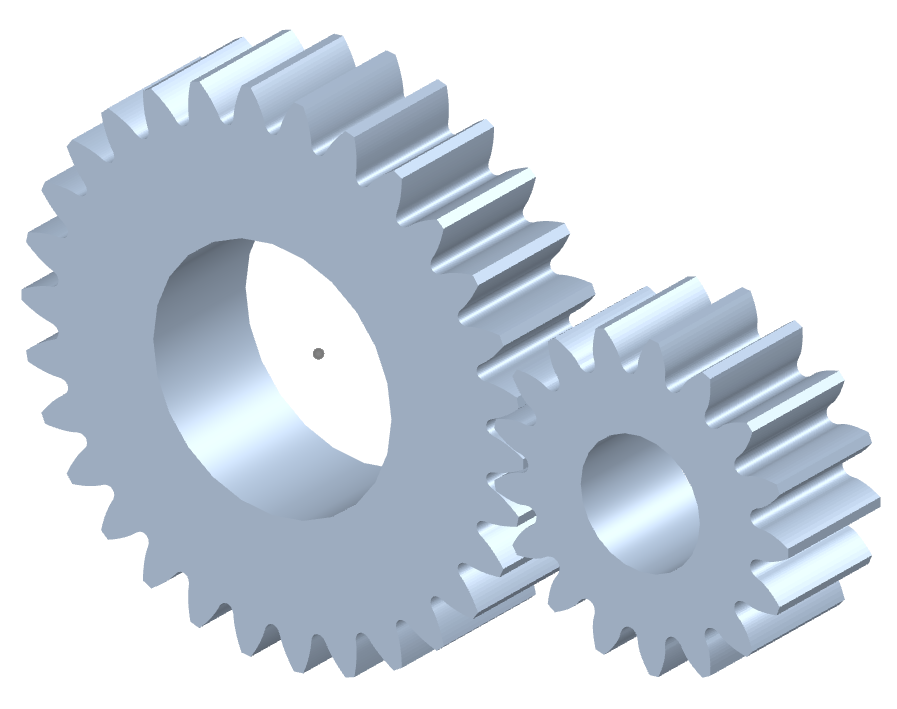
How do you ensure proper alignment when connecting spur gears?
Proper alignment is crucial when connecting spur gears to ensure smooth and efficient gear operation. Here’s a detailed explanation of how to ensure proper alignment when connecting spur gears:
- Visual Inspection: Start by visually inspecting the gears, gear shafts, and associated components for any visible misalignment or damage. Look for signs of wear, uneven tooth engagement, or any abnormalities that may affect alignment.
- Shaft Alignment: Align the gear shafts accurately before connecting the gears. Proper shaft alignment ensures that the gears are positioned correctly relative to each other. This can be achieved through various alignment techniques, such as using alignment tools, laser alignment systems, or measuring devices. The goal is to ensure parallel or coaxial alignment between the gear shafts.
- Backlash Adjustment: Adjust the backlash between the gear teeth to achieve proper alignment. Backlash refers to the slight gap between the mating teeth of gears. It is important to maintain an appropriate amount of backlash to allow for smooth gear engagement and minimize the risk of binding or jamming. Follow the manufacturer’s recommendations or industry standards for the recommended backlash range and adjust as necessary during gear installation.
- Check Gear Mesh: Verify the gear meshing pattern to ensure proper alignment. The gear teeth should mesh smoothly and evenly without any signs of excessive or uneven contact. If there are indications of improper meshing, such as concentrated contact on a specific area of the tooth, it may imply misalignment or other issues that need to be addressed.
- Shim Adjustment: If misalignment is detected, shimming can be employed to correct it. Shimming involves placing thin metal shims between the gear and the shaft to adjust the positioning and alignment. Shims are available in various thicknesses, allowing for precise alignment adjustments. Careful measurement and selection of the appropriate shim thickness can help achieve the desired alignment.
- Tightening Bolts: When connecting the gears to the shafts, ensure that the bolts or fasteners are tightened evenly and to the recommended torque specifications. Uneven tightening can introduce misalignment or uneven load distribution, leading to gear misalignment and potential issues.
- Post-Installation Verification: After connecting the gears, perform a final verification of the alignment. Rotate the gears manually or through the gear system’s intended operation and observe the gear meshing behavior. Look for any signs of abnormal noise, vibration, or irregular tooth engagement. If any issues are detected, further adjustments or inspections may be necessary.
- Regular Maintenance: Implement a proactive maintenance program that includes periodic inspections and alignment verification. Gears can experience wear or misalignment over time due to factors such as load variations, temperature changes, or prolonged operation. Regular maintenance allows for early detection and correction of alignment issues, ensuring optimal gear performance and longevity.
Proper alignment is essential for maximizing the efficiency, durability, and reliability of spur gear systems. By following these alignment practices and considering the manufacturer’s recommendations, industry standards, and expert advice, you can ensure proper alignment when connecting spur gears.
It’s important to note that the specific alignment techniques and procedures may vary depending on the gear system’s design, size, application, and other factors. Consulting with gear manufacturers, engineers, or alignment specialists can provide further guidance on the recommended alignment practices for your specific gear system.
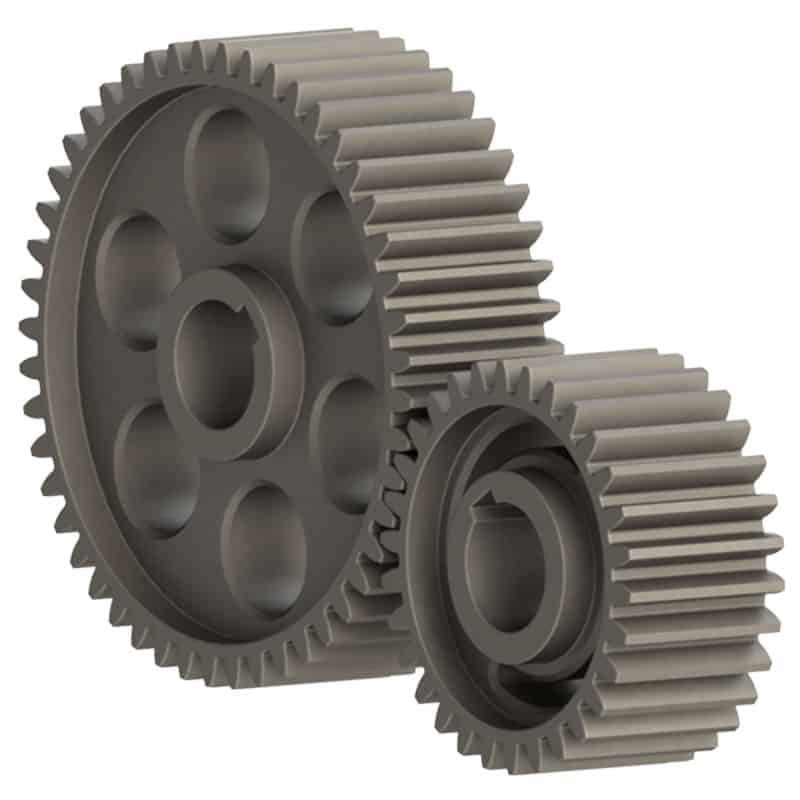
How do you install a spur gear system?
Installing a spur gear system involves several steps to ensure proper alignment, engagement, and operation. Here’s a detailed explanation of how to install a spur gear system:
- Preparation: Before installation, gather all the necessary components, including the spur gears, shafts, bearings, and any additional mounting hardware. Ensure that the gear system components are clean and free from debris or damage.
- Shaft Alignment: Proper shaft alignment is crucial for the smooth operation of a spur gear system. Ensure that the shafts on which the gears will be mounted are aligned accurately and parallel to each other. This can be achieved using alignment tools such as dial indicators or laser alignment systems. Adjust the shaft positions as needed to achieve the desired alignment.
- Positioning the Gears: Place the spur gears on the respective shafts in the desired configuration. Ensure that the gears are positioned securely and centered on the shafts. For shafts with keyways, align the gears with the key and ensure a proper fit. Use any necessary mounting hardware, such as set screws or retaining rings, to secure the gears in place.
- Checking Gear Engagement: Verify that the teeth of the gears mesh properly with each other. The gear teeth should align accurately and smoothly without any excessive gaps or interference. Rotate the gears by hand to ensure smooth and consistent meshing throughout their rotation. If any misalignment or interference is observed, adjust the gear positions or shaft alignment accordingly.
- Bearing Installation: If the spur gear system requires bearings to support the shafts, install the bearings onto the shafts. Ensure that the bearings are the correct size and type for the application. Press or slide the bearings onto the shafts until they are seated securely against any shoulder or bearing housing. Use appropriate methods and tools to prevent damage to the bearings during installation.
- Lubrication: Apply a suitable lubricant to the gear teeth and bearings to ensure smooth operation and reduce friction. Refer to the gear manufacturer’s recommendations for the appropriate lubrication type and amount. Proper lubrication helps minimize wear, noise, and heat generation in the gear system.
- Final Inspection: Once the gears, shafts, and bearings are installed, perform a final inspection of the entire spur gear system. Check for any unusual noises, misalignment, or binding during manual rotation. Verify that the gears are securely mounted, shafts are properly aligned, and all fasteners are tightened to the specified torque values.
It’s important to follow the specific installation instructions provided by the gear manufacturer to ensure proper installation and operation. Additionally, consult any applicable industry standards and guidelines for gear system installation.
By carefully following these installation steps, you can ensure a well-aligned and properly functioning spur gear system in your machinery or equipment.
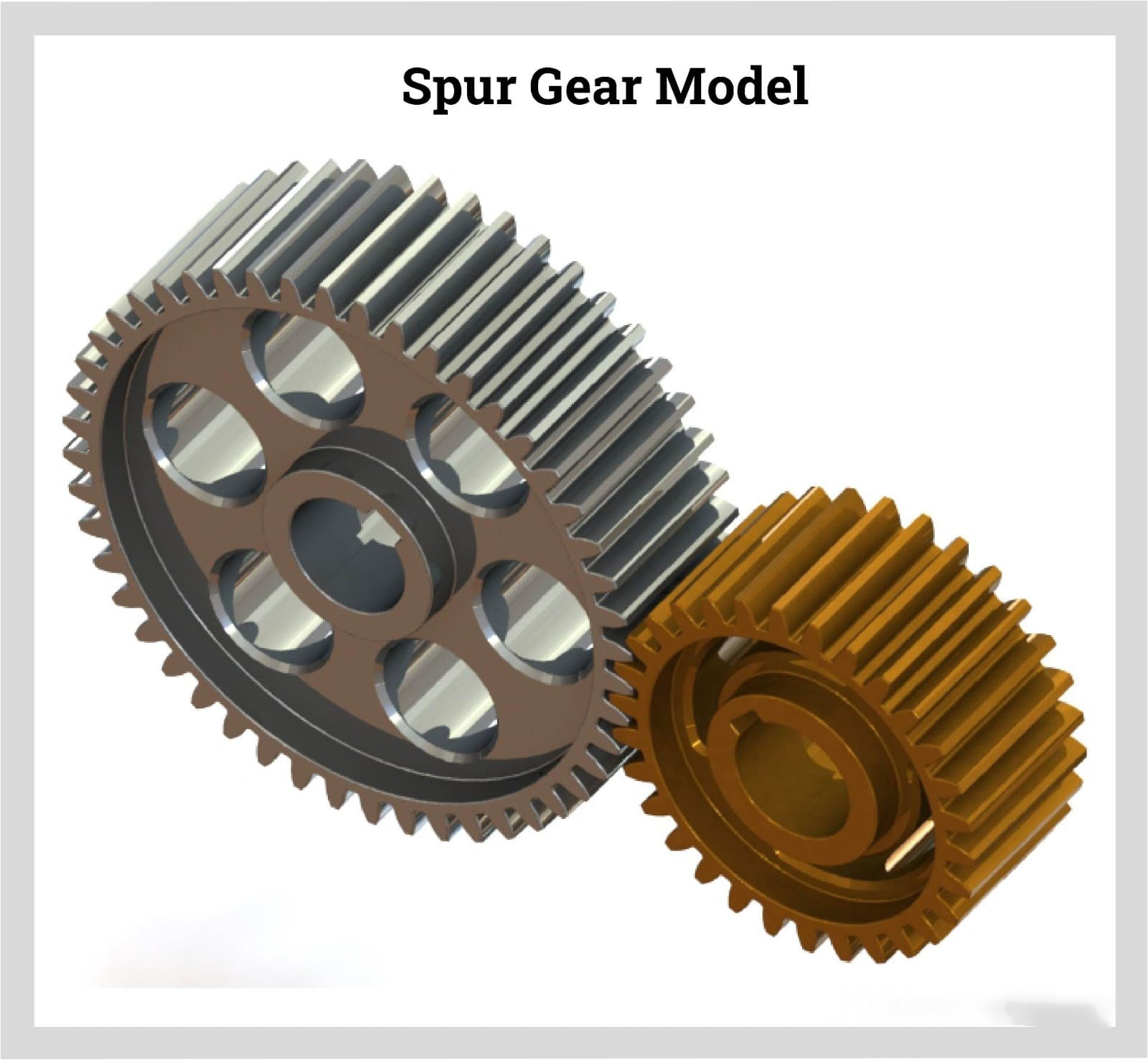
How do spur gears differ from other types of gears?
Spur gears, as a specific type of gear, possess distinct characteristics and features that set them apart from other types of gears. Here’s a detailed explanation of how spur gears differ from other types of gears:
- Tooth Geometry: One of the primary differences lies in the tooth geometry. Spur gears have straight teeth that are cut parallel to the gear axis. This differs from other gear types, such as helical gears or bevel gears, which have angled or curved teeth.
- Gear Meshing: Spur gears mesh by direct contact between their teeth, creating a line or point contact. This meshing arrangement is different from other gear types, such as worm gears or planetary gears, where the teeth mesh in a different manner, such as through sliding contact or multiple points of contact.
- Direction of Force: Spur gears transmit rotational motion and torque in a specific direction. The force is transmitted along the axis of the gears, making them suitable for parallel shaft arrangements. In contrast, other types of gears, such as bevel gears or hypoid gears, can transmit motion between non-parallel or intersecting shafts.
- Noise and Vibration: Spur gears tend to produce more noise and vibration compared to certain other gear types. The direct contact between the teeth and the sudden engagement/disengagement of the teeth can generate impact forces, leading to noise and vibration. In contrast, gear types like helical gears or double-enveloping worm gears provide smoother meshing and reduced noise levels.
- Efficiency and Load Distribution: Spur gears generally offer high efficiency in power transmission due to their direct tooth engagement. However, they may experience higher stress concentrations and load concentrations compared to other gear types. Gear designs like helical gears or planetary gears can distribute the load more evenly across the teeth, reducing stress concentrations.
- Applications: Spur gears find widespread applications in various industries and equipment. Their simplicity, ease of manufacture, and cost-effectiveness make them suitable for a wide range of systems. Other gear types have specific applications where their unique characteristics, such as high torque transmission, precise motion control, or compact size, are advantageous.
In summary, spur gears differ from other types of gears in terms of tooth geometry, gear meshing, direction of force transmission, noise and vibration characteristics, load distribution, and specific applications. Understanding these differences is crucial when selecting the appropriate gear type for a particular mechanical system, considering factors such as load requirements, motion control, efficiency, and design constraints.


editor by CX 2024-01-04