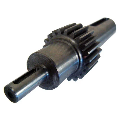
China Professional Kah-14cl3ne Harmonic Drive Servo Actuator Harmonic Gearing Servo Drive Robotic Arm Actuator Hollow Shaft Rotary Actuators bevel gear set
Product Description
Product Description
Hollow shaft rotary actuators
KAH series hollow shaft rotary actuators
Main features
1.KAH series hollow shaft rotary actuator provides large-torque and high-precision rotary actuation. With integrated design, processing and assembly technique, it is provided with high precision speed reducer, framework torque motor, hollow shaft high resolution absolute encoder, brake and intelligent sensor.
2.It provides high torque output and torque density, for example, the torque of KAH-40 rotary actuator can reach 800N·m.
3.The positioning precision of rotary actuator is within 30 Arc sec.
4.An internal through hole is set to facilitate threading wires, gas pipe and laser beams and simplify system structure.
5.Dozens of product models are provided to meet diversified needs, and the products with 220 VAC, 110 VAC and 48 VAC voltages are available.
6.The high protection grade (IP67) makes the product applicable to severe working environment.
8.It can be used by matching with KDE series EtherCAT bus servo drives to realize ultra-low vibration controland reliable and stable operation. It provides an integrated drive control solution.
Applications
The products have been widely used in such fields as electronic and semiconductor equipment, precision machine tool, factory automation systems, precision laser processing device, LED equipment, detection device, medical apparatus and instruments, robot and special mechanical arm, printing machinery, spray painting equipment, glass processing equipment, precision measuring instrument and other fields.
Model
Specifications
| KAH-14 encoder Specification parameter | |||||||
| Series | KAH-14 | ||||||
| Model KAH-14 | 14A | 14B | 14C | ||||
| Deceleration ratio | 1:51 | 1:81 | 1:101 | ||||
| Maximum torque starting &stopping(N·M) | 69 | 91 | 102 | ||||
| Instantaneous maximum torque(N·M) | 42 | 58 | 61 | ||||
| AC voltage 220VAC | Maximum speed | RPM | 119.6 | 75.3 | 60.4 | ||
| Rated speed | RPM | 60.8 | 38.3 | 30.7 | |||
| Maximum current | Arms | 4.53 | 3.89 | 3.41 | |||
| Rated current | Arms | 2.12 | 1.85 | 1.56 | |||
| Torque constant | N·M/Arms | 19.81 | 31.35 | 39.10 | |||
| Motor phase resistance | Ohms | 2.135 | |||||
| Motor phase inductance | mH | 3.869 | |||||
| Motor Back EMF | Vrms/kRPM | 30.66 | |||||
| AC voltage 1100VAC | Maximum speed | RPM | 100 | 63.0 | 50.5 | ||
| Rated speed | RPM | 60.8 | 38.3 | 30.7 | |||
| Maximum current | Arms | 9.49 | 7.87 | 7.08 | |||
| Rated current | Arms | 4.28 | 3.72 | 3.14 | |||
| Torque constant | N·M/Arms | 9.82 | 15.61 | 19.45 | |||
| Motor phase resistance | Ohms | 1.036 | |||||
| Motor phase inductance | mH | 1.684 | |||||
| Motor Back EMF | Vrms/kRPM | 14.79 | |||||
| AC voltage 480VAC | Maximum speed | RPM | 78.4 | 49.4 | 39.6 | ||
| Rated speed | RPM | 60.8 | 38.3 | 30.7 | |||
| Maximum current | Arms | 17.89 | 18.86 | 13.33 | |||
| Rated current | Arms | 10.88 | 12.03 | 7.97 | |||
| Torque constant | N·M/Arms | 3.86 | 4.82 | 7.65 | |||
| Motor phase resistance | Ohms | 0.262 | |||||
| Motor phase inductance | mH | 0.313 | |||||
| Motor Back EMF | Vrms/kRPM | 7.98 | |||||
| Absolute Encoder | Encoder Type | Hollow absolute multiturn encoders ,Single-loop 19,22or24, multiturn16 | |||||
| Encoder resolution Motor(1time)rotation | 219(524,288),222(4,194.304)or224(16777216) | ||||||
| Motor multiple rotation counter | 215(65.536) | ||||||
| Incremental | Encoder resolution | Hollow incremental encoder,40000impulse/rpm(4 time signal) | |||||
| encoder | Output shaft resolution | pulse/rev | 2040000 | 3240000 | 4040000 | ||
| uniderection positioning accuracy | Arc Sec | 60 | 40 | 40 | |||
| Bidirectional positioning accuracy | Arc Min | 2 | 1.5 | 1 | |||
| Overturning stiffness | ×104 N·m /rad | 22.5 | 27.3 | ||||
| Torsional stiffness | ×104 N·m /rad | 1.8 | 2.3 | ||||
| Moment of inertia | without Brake | Kg*m2 | 0.19 | 0.57 | 0.86 | ||
| with Brake | Kg*m2 | 0.22 | 0.63 | 0.95 | |||
| Weight | without Brake | Kg | 2.2 | ||||
| with Brake | Kg | 2.5 | |||||
| Motor Grade | 16 | ||||||
| Motor insulation | Heat resistance grade :F(155ºC) | ||||||
| Insulation resistance:above200MΩ(DC500V) | |||||||
| Dielectric Strength:AC1500V/1min | |||||||
| Protection grade | Fully closed self cooling type(IP65/IP67 degree) | ||||||
Photos
/* March 10, 2571 17:59:20 */!function(){function s(e,r){var a,o={};try{e&&e.split(“,”).forEach(function(e,t){e&&(a=e.match(/(.*?):(.*)$/))&&1
| Application: | Motor, Machinery |
|---|---|
| Hardness: | Hardened Tooth Surface |
| Installation: | Vertical Type |
| Samples: |
US$ 3000/Piece
1 Piece(Min.Order) | Order Sample |
|---|
| Customization: |
Available
| Customized Request |
|---|
.shipping-cost-tm .tm-status-off{background: none;padding:0;color: #1470cc}
|
Shipping Cost:
Estimated freight per unit. |
about shipping cost and estimated delivery time. |
|---|
| Payment Method: |
|
|---|---|
|
Initial Payment Full Payment |
| Currency: | US$ |
|---|
| Return&refunds: | You can apply for a refund up to 30 days after receipt of the products. |
|---|
Can you explain the impact of gear shaft misalignment on gear performance?
Gear shaft misalignment can have a significant impact on the performance of gears within a system. When gear shafts are not properly aligned, several issues can arise, affecting the overall functionality and reliability of the gears. Let’s explore the impact of gear shaft misalignment in detail:
- Reduced Efficiency:
Misalignment causes a loss of efficiency in gear systems. When gear shafts are misaligned, the teeth of the gears do not mesh correctly, leading to increased friction and energy losses. This results in reduced power transmission efficiency, as a portion of the input power is dissipated as heat instead of being effectively transferred through the gears.
- Increased Wear and Fatigue:
Misalignment can lead to uneven contact and loading between gear teeth. This uneven distribution of forces causes localized high-stress areas on the gear teeth, leading to accelerated wear and fatigue. The concentrated stress on specific areas of the teeth can result in pitting, wear, and even tooth breakage over time. Increased wear and fatigue significantly reduce the lifespan of gears and can lead to unexpected failures.
- Noise and Vibration:
Gear shaft misalignment often results in increased noise and vibration levels within the gear system. As the misaligned teeth engage, they generate excessive noise due to impact and increased friction. The vibrations caused by the misalignment can propagate through the gear assembly and the surrounding components, causing additional noise and potentially affecting the performance and lifespan of the entire system.
- Loss of Tooth Contact:
Misalignment can cause a loss of proper tooth contact between the gears. Insufficient tooth contact reduces the load-carrying capacity of the gears and compromises the transmission of torque. The reduced contact area also increases the likelihood of localized stress concentrations, leading to premature wear and failure.
- Overloading and Unbalanced Loads:
Gear shaft misalignment can result in overloading and unbalanced loads on the gears. Misalignment can cause uneven distribution of forces, with some teeth bearing a higher load than others. This can lead to excessive stress on specific gear teeth, potentially exceeding their load-carrying capacity. Over time, the overloading of certain teeth can result in accelerated wear, tooth breakage, and even catastrophic gear failure.
- Seal and Bearing Issues:
Misalignment can also affect the performance of seals and bearings within the gear system. Misaligned gear shafts can create additional radial or axial loads on the bearings, reducing their lifespan and causing premature failure. Seal integrity can also be compromised, leading to leaks and contamination of the gear system, further exacerbating the issues associated with misalignment.
In summary, gear shaft misalignment has a detrimental impact on gear performance. It reduces efficiency, increases wear and fatigue, generates noise and vibration, causes loss of tooth contact, leads to overloading and unbalanced loads, and affects the performance of seals and bearings. Proper alignment of gear shafts is crucial to ensure optimal gear performance, longevity, and reliable power transmission within the gear system.
What are the factors to consider when designing gear shafts for specific applications?
Designing gear shafts for specific applications requires careful consideration of various factors to ensure optimal performance and reliability. Let’s explore the key factors that should be taken into account during the design process:
- Load and Torque Requirements:
The load and torque requirements of the specific application are crucial considerations. Understanding the maximum load the gear shaft will experience and the torque it needs to transmit is essential for selecting appropriate materials, determining the required dimensions, and ensuring the gear shaft can handle the anticipated forces effectively.
- Gear Type and Configuration:
The gear type and configuration directly influence the design of the gear shaft. Different gear types, such as spur gears, helical gears, bevel gears, or worm gears, have unique characteristics that impact the design considerations for the gear shaft. Factors such as gear tooth profile, pitch, pressure angle, and gear ratio need to be taken into account during the design process to ensure proper alignment, engagement, and efficient power transmission.
- Material Selection:
Selecting the appropriate material for the gear shaft is crucial for its strength, durability, and performance. Factors such as the required strength, wear resistance, fatigue resistance, and corrosion resistance should be considered when choosing the material. Common materials for gear shafts include various steels, alloys, and sometimes specialized materials like bronze or brass, depending on the specific application requirements.
- Shaft Dimensions and Geometry:
The dimensions and geometry of the gear shaft need to be carefully determined. Factors such as shaft diameter, length, keyways, chamfers, and fillets are important considerations. Proper shaft dimensions and geometry ensure sufficient strength, proper fit within the gear assembly, and compatibility with other components within the system.
- Bearing Support and Lubrication:
The gear shaft design should incorporate provisions for bearing support and lubrication. Bearings placed along the gear shaft help reduce friction, support the shaft under load, and ensure smooth rotation. Adequate lubrication, such as oil or grease, is necessary to minimize wear between the gear shaft and bearings, as well as to reduce heat generation and promote efficient operation.
- Heat Treatment and Surface Finish:
Depending on the application requirements, heat treatment processes like quenching and tempering may be applied to enhance the mechanical properties of the gear shaft. Heat treatment can improve hardness, strength, and toughness, increasing the gear shaft’s ability to withstand high loads and resist wear. Additionally, considering the surface finish of the gear shaft can help reduce friction, improve gear meshing, and minimize the risk of surface damage.
- Manufacturability and Cost:
Designing gear shafts should also take into account manufacturability and cost considerations. The design should be feasible for manufacturing processes such as machining, forging, or casting, depending on the chosen material and complexity of the design. The design should also aim to optimize material usage and minimize manufacturing costs while meeting the required performance criteria.
In summary, when designing gear shafts for specific applications, factors such as load and torque requirements, gear type and configuration, material selection, shaft dimensions and geometry, bearing support and lubrication, heat treatment and surface finish, as well as manufacturability and cost considerations, should all be carefully evaluated. By considering these factors, a well-designed gear shaft can be developed to meet the specific needs of the application, ensuring reliable and efficient power transmission within the gear system.
What industries commonly use gear shafts in their applications?
Gear shafts find applications in various industries where the transmission of motion and power is necessary. They are widely utilized in numerous sectors that rely on machinery and mechanical systems. Here are some industries that commonly use gear shafts in their applications:
- Automotive Industry:
The automotive industry extensively uses gear shafts in vehicles. Gear shafts are present in the transmission systems, where they transmit power and torque between the engine and the wheels. They enable gear shifting, torque conversion, and speed control, contributing to the overall performance and drivability of automobiles.
- Industrial Manufacturing:
Industrial manufacturing sectors, such as machinery manufacturing, rely heavily on gear shafts. They are used in various types of machinery, including lathes, milling machines, conveyor systems, and assembly lines. Gear shafts enable power transmission, motion control, and torque conversion in these machines, facilitating the production and processing of goods.
- Aerospace and Defense:
In the aerospace and defense industries, gear shafts are crucial components in aircraft engines, helicopters, and military vehicles. They play a vital role in transmitting power and torque between the engines and propellers or rotors, providing the necessary thrust and control. Gear shafts in these applications must meet stringent performance and reliability requirements.
- Power Generation:
Gear shafts are utilized in power generation industries, including thermal power plants, hydroelectric plants, and wind turbines. They facilitate the transfer of rotational motion and torque from turbines or generators to power transmission systems. Gear shafts in these applications often handle high-power outputs and must be designed to withstand demanding operating conditions.
- Construction and Mining:
The construction and mining industries commonly employ gear shafts in heavy machinery and equipment. Gear shafts are found in excavators, bulldozers, cranes, and drilling rigs, among others. They enable power transmission and torque conversion, allowing these machines to perform tasks such as digging, lifting, and drilling with precision and efficiency.
- Marine and Shipbuilding:
Gear shafts are essential components in marine applications, including ships, boats, and marine propulsion systems. They are utilized in marine engines, propellers, and thrusters, enabling the transmission of power and torque for propulsion and maneuvering. Gear shafts in marine environments must be corrosion-resistant and capable of withstanding the harsh conditions of saltwater and vibrations.
- Renewable Energy:
In the renewable energy sector, gear shafts are used in wind turbines and solar tracking systems. They facilitate the transfer of rotational motion and torque from wind or solar power sources to generators or energy storage systems. Gear shafts play a vital role in converting and optimizing the energy generated from renewable sources.
These are just a few examples of industries that commonly use gear shafts in their applications. Gear shafts are versatile components that are integral to the functioning of machinery and mechanical systems across various sectors.


editor by CX 2024-01-11