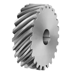
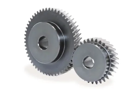
China Standard High Quality Spur Worm Helical Hypoid Bevel Pinion Gear for Industrial Usage straight bevel gear
Product Description
We are a professional company in bulk material handling, transportation, storage, processing, accessory equipment design, integration and manufacturing. We can provide a complete set of solutions. Thank you for reading the information and welcome to purchase! Welcome to agent distribution!
Brief introduction of the company’s manufacturing capacity
The company’s headquarters, technology and sales are located in Lingang New Area of China (ZheJiang ) pilot free trade zone,The company’s manufacture base is located in Xihu (West Lake) Dis. county, ZHangZhoug Province, which is known as “the most beautiful county in China”. It is 65 kilometers away from HangZhou city and 60 kilometers away from Qiandao Lake. The transportation to Xihu (West Lake) Dis. county from other places is very convenient. No matter by railway, highway or waterway. The manufacture base has a total plant area of around 30000 square CHINAMFG and workshop is equipped with more than 300 sets of various advance manufacture equipment, including 20 sets of CNC precision vertical lathe MODEL: SMVTM12000×50/150, CNC vertical lathe MODEL:DVT8000×30/32, CNC horizontal lathe, MODEL: CK61315×125/32, CNC horizontal lathe MODEL:CK61200×80/32, CNC Grounding boring and milling machine MODEL:TJK6920,etc.Most of the parts are machined by using CNC machine equipment. Theis is a hot treatment CHINAMFG with size 10.5m×8m×8m. The manufacture base also equipped with lifting capacity of 25t, 50t, 100t, 200t overhead crane to handle heavy workpiece and assembly work.
Metalworking equipment
| Name of equipment | Model number | Quantity | SCOPE of application | |
| A | Lathes | |||
| 1 | Vertical Lathe | Numerical control | 1 | Φ 12000 |
| 2 | Vertical Lathe | Numerical control | 1 | Φ 8000 |
| 3 | Vertical Lathe | 1 | Φ 1600 | |
| 4 | Vertical Lathe | C5112A | 1 | Ф 1250 |
| 5 | Horizontal Lathe | Numerical control | 1 | CK61315×12×100T |
| 6 | Horizontal Lathe | CW61200 | 1 | Ф 2000×8000 |
| 7 | Horizontal Lathe | CW61160 | 1 | Ф 1600×6500 |
| 8 | Horizontal Lathe | CW6180 | 2 | Ф 800×3000 |
| 9 | Horizontal Lathe | CW61125 | 2 | Ф 1250×5000 |
| 10 | Horizontal Lathe (remodel) | CW62500 | 2 | Ф 2800×6000 |
| 11 | Common Lathe | CY6140 | 3 | Ф 400×1000 |
| 12 | Common Lathe | CA6140 | 3 | Ф 400×1500 |
| 13 | Common Lathe | C620 | 2 | Ф 400×1400 |
| 14 | Common Lathe | C616 | 1 | Ф 320×1000 |
| 15 | Common Lathe | C650 | 1 | Ф 650×2000 |
| B | Drilling machine | |||
| 1 | Radial drilling machine | Z3080 | 3 | Ф 80×2500 |
| 2 | Radial drilling machine | Z3040 | 2 | Ф 60×1600 |
| 3 | Universal drilling machine | ZW3725 | 3 | Ф 25×880 |
| C | Planing machine | |||
| 1 | Shaper | B665 | 1 | L650 |
| 2 | Hydraulic Shaper | B690 | 1 | L900 |
| 3 | Gantry Planer | HD–16 | 1 | L10000×B1600 |
| D | Milling Machine | |||
| 1 | 4 Coordinate Milling Machine | Numerical control | 1 | 2500×4000 |
| 2 | Gantry milling machine | Numerical contro | 1 | 16mx5mx3m |
| 3 | Gantry milling machine | Numerical contro | 1 | 12mx4mx2.5m |
| 4 | Gantry milling and boring machine | Numerical contro | 1 | Φ 250 |
| 5 | Vertical Milling Machine | XS5054 | 1 | 1600×400 |
| 6 | Horizontal Milling Machine | C62W | 1 | 1250×320 |
| 7 | Horizontal Milling Machine | X60 | 1 | 800×200 |
| 8 | Gantry milling machine | X2014J | 1 | L4000×B1400 |
| 9 | Gantry milling machine | X2571J | 1 | L3000×B1000 |
| 10 | Floor end milling | TX32-1 | 1 | L1500×H800 |
| E | Grinding machine | |||
| 1 | External Grinder | M131W | 1 | Ф 300×1000 |
| 2 | External Grinder | M1432B | 1 | Ф 320×15000 |
| 3 | Surface Grinder | M7130 | 1 | L 1000×300 |
| 4 | Tool grinder | M6571C | 1 | Ф 250 |
| F | Boring machine | |||
| 1 | Floor-standing milling and boring machine | TJK6920 | 1 | X12000 × Y4500 × Z1000 |
| 2 | Boring machine | TSPX619 | 1 | Ф 1000 |
| 3 | Boring machine | T616 | 1 | Ф 800 |
| 4 | Boring machine | T611 | 1 | Ф 800 |
| G | Slotted bed | |||
| 1 | Slotted bed | B5032 | 1 | H320 |
| H | Other machine tools | |||
| 1 | Gear hobbing machine | Y3150 | 1 | Ф 500 M=6 |
| 2 | Hacksaw machine | G7571 | 1 | Ф 220 |
Products and services available
Material handling equipment
Storage equipment
Conveying equipment
Feeding equipment
Component of conveying system
Belt conveyor parts
Large and medium sized finishing parts
If you need above products, please contact us!
ZheJiang Sunshine Industrial Technology Co. , Ltd.
/* January 22, 2571 19:08:37 */!function(){function s(e,r){var a,o={};try{e&&e.split(“,”).forEach(function(e,t){e&&(a=e.match(/(.*?):(.*)$/))&&1
| Application: | Motor, Electric Cars, Motorcycle, Machinery, Marine, Toy, Agricultural Machinery, Car, Customization |
|---|---|
| Hardness: | Customization |
| Gear Position: | Customization |
.shipping-cost-tm .tm-status-off{background: none;padding:0;color: #1470cc}
|
Shipping Cost:
Estimated freight per unit. |
about shipping cost and estimated delivery time. |
|---|
| Payment Method: |
|
|---|---|
|
Initial Payment Full Payment |
| Currency: | US$ |
|---|
| Return&refunds: | You can apply for a refund up to 30 days after receipt of the products. |
|---|
How do you prevent backlash and gear play in a helical gear mechanism?
In a helical gear mechanism, preventing backlash and gear play is crucial to ensure accurate motion control, minimize vibration, and maintain the overall efficiency of the system. Here’s a detailed explanation of how to prevent backlash and gear play in a helical gear mechanism:
- Proper Gear Pair Alignment: Ensuring proper alignment of the gear pairs is essential to minimize backlash and gear play. Precise alignment helps to achieve optimal contact between the helical gear teeth, reducing gaps and potential for play. Proper alignment can be achieved through accurate positioning of the gear shafts and the use of alignment tools, such as dial indicators or laser alignment systems.
- Preload or Axial Play Adjustment: Applying a preload to the helical gears can help eliminate backlash and gear play. Preload refers to the intentional application of a force that compresses the gear mesh, ensuring a tight fit between the gear teeth. This can be achieved by using adjustable bearings, shims, or axial play adjustment mechanisms to control the axial position of the gears. By applying an appropriate preload, the gear teeth are kept in constant contact, minimizing any play or backlash.
- Accurate Gear Tooth Profile: High-quality manufacturing and accurate tooth profile design are essential to minimize backlash and gear play. The tooth profile should be precisely calculated to ensure proper engagement and minimal clearance between the gear teeth. This includes considerations such as the helix angle, tooth thickness, and tooth contact pattern. By using well-designed gear teeth with tight tolerances, backlash and gear play can be significantly reduced.
- Proper Gear Mesh Lubrication: Adequate lubrication is critical to reduce friction, wear, and the potential for backlash in helical gears. The lubricant helps to create a thin film between the mating gear surfaces, ensuring smooth and consistent gear meshing. Proper lubrication also helps to dissipate heat generated during operation, preventing gear tooth damage. The selection of a suitable lubricant and regular maintenance of the lubrication system are essential to prevent backlash and ensure optimal gear performance.
- Stiff Gearbox Design: A stiff and rigid gearbox design can help minimize gear play and backlash. The gearbox housing and supporting structures should be designed to withstand the forces and loads generated during operation. This prevents any flexing or movement of the gear components, ensuring stable gear meshing and minimizing the potential for backlash. Stiffening measures can include using robust materials, adequate bracing, and reinforcing the gearbox housing.
- Regular Maintenance and Inspection: Regular maintenance and inspection of the helical gear mechanism are essential to prevent backlash and gear play. This includes checking for any signs of wear, misalignment, or damage in the gear teeth, bearings, and housing. Any worn or damaged components should be promptly replaced to maintain the integrity of the gear system. Regular lubrication and cleanliness of the gears also contribute to minimizing backlash and ensuring smooth operation.
By implementing these preventive measures, engineers can effectively minimize backlash and gear play in a helical gear mechanism. This results in improved precision, reduced vibration, and enhanced overall efficiency of the gear system.
What are the environmental considerations when using helical gears?
When using helical gears, several environmental considerations should be taken into account. These considerations primarily focus on reducing the environmental impact associated with gear manufacturing, operation, and maintenance. Here is a detailed explanation of the environmental considerations when using helical gears:
- Material Selection: The choice of materials for helical gears can have an environmental impact. Opting for materials that are recyclable, have a low carbon footprint, or are sourced from sustainable and responsible suppliers can help minimize the environmental footprint of gear production.
- Energy Efficiency: Helical gears can contribute to energy efficiency in machinery and equipment. By using helical gears with high efficiency, the overall energy consumption can be reduced, resulting in lower greenhouse gas emissions and energy-related environmental impacts.
- Lubrication: Proper lubrication of helical gears is essential for efficient operation and reducing wear. Choosing environmentally friendly lubricants, such as biodegradable or low-toxicity options, can minimize the potential harm to the environment in case of leakage or disposal.
- Maintenance and Inspection: Regular maintenance and inspection of helical gears can help identify and address issues such as misalignment, excessive wear, or inadequate lubrication. Promptly addressing these issues can extend the gear’s lifespan, reduce the need for replacements, and reduce waste generation.
- Noise and Vibration: Helical gears are known for their smooth operation, which helps reduce noise and vibration. This can have environmental benefits by minimizing noise pollution and creating a more comfortable and sustainable working environment.
- End-of-Life Considerations: When helical gears reach the end of their useful life, proper disposal or recycling practices should be followed. Recycling gears and their materials can help reduce waste and prevent the accumulation of non-biodegradable materials in landfills.
- Life Cycle Assessment: Conducting a life cycle assessment (LCA) of helical gears can provide a comprehensive evaluation of their environmental impact throughout their life cycle. This assessment considers factors such as raw material extraction, manufacturing processes, energy consumption, transportation, use phase, and end-of-life disposal. LCA can help identify areas for improvement and guide decision-making towards more sustainable gear solutions.
By considering these environmental factors when using helical gears, manufacturers and users can minimize the environmental impact associated with gear production, operation, and disposal. Implementing sustainable practices not only helps protect the environment but also promotes resource efficiency and long-term economic viability.

Are there different types of helical gears available?
Yes, there are different types of helical gears available to meet specific application requirements. Here’s a detailed explanation of some common types of helical gears:
- Parallel Helical Gears: Parallel helical gears are the most commonly used type of helical gears. In this configuration, two helical gears with parallel axes are meshed together. They transmit power and motion between parallel shafts. Parallel helical gears provide smooth operation, high load-carrying capacity, and efficient power transmission.
- Double Helical Gears (Herringbone Gears): Double helical gears, also known as herringbone gears, have two sets of helical teeth that are placed in a V-shaped configuration. The V-shaped teeth face each other, with a groove or gap in the middle. This design cancels out the axial thrust that is generated by the helical gear’s inclined teeth. Double helical gears are often used in applications that require high torque transmission and axial load balancing, such as heavy machinery and marine propulsion systems.
- Crossed Helical Gears (Screw Gears): Crossed helical gears, also referred to as screw gears, involve the meshing of two helical gears with non-parallel and non-intersecting axes. The gears are oriented at an angle to each other, typically 90 degrees. Crossed helical gears are used in applications where shafts intersect or when a compact and non-parallel gear arrangement is required. They are commonly found in hand drills, speedometers, and some mechanical watches.
- Skew Gears: Skew gears are a type of helical gear in which the gear teeth are cut at an angle to the gear axis. The angle of the teeth can vary, allowing for different degrees of skew. Skew gears are used in applications where the axes of the mating gears are neither parallel nor intersecting. They can transmit power between non-parallel and non-intersecting shafts while accommodating misalignments.
- Helical Rack and Pinion: A helical rack and pinion system consists of a helical gear (pinion) that meshes with a linear gear (rack). The pinion is a cylindrical gear with helical teeth, while the rack is a straight bar with teeth that mesh with the pinion. This configuration is commonly used in applications that require linear motion, such as CNC machines, robotics, and rack and pinion steering systems in automobiles.
- Variable Helix Gears: Variable helix gears have a unique tooth profile where the helix angle varies along the face width of the gear. The varying helix angle helps to reduce noise, vibration, and backlash while maintaining smooth operation and load distribution. These gears are often used in high-performance applications where noise reduction and precise motion control are critical.
The specific type of helical gear used depends on factors such as the application requirements, load conditions, space limitations, and desired performance characteristics. Manufacturers often provide various options and customizations to meet specific needs.
It’s important to note that the design and manufacturing of helical gears require careful consideration of factors such as tooth profile, helix angle, lead angle, module or pitch, pressure angle, and material selection. These factors ensure proper gear meshing, load distribution, and efficient power transmission.
In summary, different types of helical gears, including parallel helical gears, double helical gears (herringbone gears), crossed helical gears (screw gears), skew gears, helical rack and pinion systems, and variable helix gears, are available to cater to a wide range of applications. Each type has its unique characteristics and advantages, allowing for optimized performance and reliable power transmission in various industries and machinery.


editor by CX 2024-04-08